


INTRODUCTION
During the mid-1960s, the aggressive efforts of the Soviet Union to expand its intercontinental ballistic missile (ICBM) force, improve its accuracy, and develop an effective anti-ballistic missile defense led to a re-evaluation of the survivability of the U.S. land-based nuclear forces. In late 1966, the Pentagon undertook a study called Strategic Experimental (or STRAT-X) to consider a range of possible future nuclear weapons. It was a national effort of great influence and led over time to the sea-based component of the nuclear triad, multi-warhead ICBMs, and increased hardness; it was the inspiration for both the MX Peacekeeper ICBM and the Trident submarine-launched ballistic missile [1].
The Air Force, under both the Carter and Reagan administrations, pursued development of a successor missile system to Minuteman III that would provide increased range, variable warhead yields, improved accuracy, and improved survivability [2]. There were many discussions in the mid-1970s about whether the primary purpose of the MX program was to develop a new missile of highly improved accuracy and payload capability or whether the primary objective was to make the system more survivable. While it was generally agreed that both parts of this problem had to be solved, in almost everyone’s mind, the primary objective of the MX program was to make a new generation of ICBMs more survivable. Because each of the basing modes under consideration was susceptible to some type of damaging nuclear weapon effect, the Defense Nuclear Agency (DNA) (now the Defense Threat Reduction Agency [DTRA]) played a central role in the Air Force’s basing deliberations.
DNA’S PARTNERSHIP WITH THE AIR FORCE
Considering that survivability was primarily an issue of nuclear weapons effects, it was inevitable that DNA would play a significant role in the Air Force’s basing deliberations. As it happened, the Air Force Ballistic Missile Office (BMO) looked to the agency to fund the requisite Nuclear Hardness and Survivability (NH&S) effort for each of the basing concepts on the basis that “that was DNA’s business.” The DNA Deputy Director for Science and Technology (DDST) at the time, the late Peter Haas, said he would be pleased to support the Air Force as long as it agreed to take DNA along with DNA’s money.
So, DNA and BMO partnered for more than a decade to identify a survivable and acceptable basing mode for the MX missile. As the particular nuclear weapon effect vulnerability for a basing concept was identified, DNA undertook necessary analyses and tests to gather data and determine the viability of the concept. For example, certain design considerations for the multiple protective system (MPS) were to ensure compatibility with strategic arms limitations (e.g., viewing ports in the tops of each shelter allowed Soviet national technical means to assure themselves that there was not a missile inside). The reason for such complications was that it was assumed at that time that the Soviets would never agree to on-site inspections.
Probably the three greatest contributions DNA made to the basing programs were (1) development and definition of the nuclear environments specific to each basing system, (2) proof-of-principal tests demonstrating crucial survivability conditions for the small ICBM (SICBM) based in hardened mobile launchers, and (3) development of superhard silo technology in combination with a fundamental reinterpretation of nuclear cratering data and high-shock-strength airblast propagation. The following sections discuss each of these contributions.
BASING ALTERNATIVES
The United States has considered many possible missile basing modes since the early 1960s, beginning with the STRAT-X study in 1966–67. Most fall into two categories: (1) free mobile systems in which missiles are moved on trains, trucks, aircraft, submarines, etc., over large areas (often hundreds of thousands of square miles) and are not tied to fixed shelters; and (2) multiple aim point (MAP) systems in which missiles are shuttled among a large number of potential launch sites. Preliminary design was begun on such shelter systems, including (1) a continuous shallow-buried trench several miles in length, and (2) a MPS in which some number of missiles are randomly distributed among a much larger number of shelters.
In 1980, the Office of the Secretary of Defense (OSD) published a summary of 30 different missile basing concepts, identifying both positive and negative evaluation factors for each [3]. The concepts ranged from (1) no rebasing (launch under attack, orbital-based), (2) water-based (shallow underwater, inland ships, ocean ships, etc.), (3) aircraft-based (short takeoff and landing aircraft, vertical takeoff and landing aircraft, dirigible, etc.), and (4) land-based (proliferated, unsheltered, superhard, trench, MPS). The latter category contains 18 separate concepts including 5 separate MPS systems.
MAP Concepts
Covered Trench
The shallow buried trench (covered trench) basing envisaged the MX on a mobile launcher moving within a miles-long, near-surface-covered trench. The question arose as to whether it was possible for a nuclear fireball intersecting the trench to cause the trench to act as a nuclear shock tube along its entire length. This concern gave rise to the HYBLA GOLD nuclear underground test to answer this question.
The HYBLA GOLD test was conceived, designed, and executed successfully in record time. The test bed consisted of five air-filled concrete shock tubes coupled to a single nuclear device. The primary objective was to obtain detailed measurements of high-enthalpy plasma behavior in these shock tubes; a secondary objective was the evaluation of instrumentation for such measurements [4].
Measurements were of three basic types: close-in pressure, pipe-wall pressure, and pipe-wall ablation. This event marked the first successful use of Manganin pressure gauges in the close-in nuclear environment. The steel flatpack pressure gauges met the design requirement of long recording times, which ranged from 800 ps to greater than 2.5 ms, with 38 of the 40 pipe-wall pressure gauges working properly at shot time. Pipe-wall pressures were substantially lower than pre-shot predictions; attenuation of plasma pressure with range along the shock tubes was higher than predicted. SRI International ablation gauges were a new concept designed for HYBLA GOLD. A total of 33 channels were fielded; 32 worked properly at shot time. In addition to providing data on pipe ablation depth vs. time, these gauges provided data on plasma conductivity and secondary low-resolution information on pipe pressure, pipe-wall strain, and pipe-wall temperature. Inferred ablation rates were orders of magnitude higher than pre-shot predictions.
It was concluded that natural attenuation mechanisms within the trench likely would mitigate shock-tube-like effects on the missile to where conventional protective measures (e.g., blast plugs fore and aft of the missile) were practical.
Another potential vulnerability was progressive collapse of the tunnel from external airblast loading, a so-called “toothpaste tube” effect. These questions were never finally answered, as development of the trench concept was not pursued.
MPS Concepts
The evaluation of the MX/MPS basing concept identified no negative features. As adopted by the Carter administration, 200 MX missiles and launchers would be moved at random among 4,600 shelters in Nevada and Utah. The shelters are located about a mile apart and hardened to a level in which a direct hit on one will not disable another shelter or a hit between shelters would not damage two or more shelters. In concept, the shelter can be either horizontal or vertical. The vertical arrangement offers greater hardness at slightly lower cost; the horizontal geometry offers much more rapid relocation and allows for certain Strategic Arms Limitations Treaty (SALT) verification procedures. The shelters, some support facilities, and portions of two main operating bases are fenced and restricted from public use. The total restricted area occupies about 25–33 square miles. The remaining land is available to the public as before for grazing, agriculture, mining, recreation, etc. The total land area defined by the perimeter of the 200 clusters would have been approximately 8,000 square miles [5].
A number of high-explosive (HE) field tests were conducted to verify MPS shelter designs. The so-called SALT viewing ports in the horizontal shelters were a major complication since they interfered with the structural continuity of the shelter and added to its complexity and cost. There were also lingering questions as to whether the SALT ports as implemented in the fielded design compromised the shelter’s design hardness.
When the Reagan administration came into office in 1981, it ordered a new look at the MX program and a re-evaluation of the decision to build the MPS system due to concerns ranging from preserving location uncertainty to outguessing the Soviet threat, as well as environmental impacts. President Reagan convened a blue-ribbon panel under the late Dr. Charles Townes to review once again all of the basing mode options. DNA served in a liaison role with the panel and briefed several alternative schemes involving superhard silo designs and deep underground basing. Dr. Townes recommended pursuing the design of a patterned configuration of superhard silos in a dense-packed array where fratricide acts to defeat the attack, as well as deep underground basing. Following the report of the Townes Panel, President Reagan cancelled the Carter MPS system. Preliminary design work continued on dense-packed and deep underground basing, but neither design concept reached a final design phase.
The second panel created by President Reagan was the President’s Commission on Strategic Forces, chaired by Brent Scowcroft [6]. Chairman Scowcroft undertook a substantially more expansive look at our strategic nuclear forces, essentially decoupling missile vulnerability from near-term MX/Peacekeeper deployment. He recommended that, as an interim measure, 100 MX missiles be deployed in existing Minuteman silos and viewed as a modernization of the force, replacing the 100 Minuteman and the Titan II missiles being decommissioned. He also recommended that engineering design be initiated on a single-warhead ICBM, leading to full-scale development in 1987 and initial operating capability in the early 1990s, and that hardened silos or shelters and hardened mobile launchers be investigated as possible basing modes. In addition, he recommended that a program be undertaken to resolve the uncertainties regarding silo or shelter hardness, leading to later decisions about hardening MX in silos and deploying a small single-warhead ICBM in hardened silos or shelters. Finally, Chairman Scowcroft proposed that vigorous investigation proceed on different types of land-based vehicles and launchers, particularly including hardened vehicles. President Reagan fully endorsed the Scowcroft report in a letter to Congress [7].
The U.S. Congress was a major player in the MX program during both the Carter and Reagan administrations [8–11]. In the Defense Authorization Act of 1986, OSD was directed to “ … conduct an independent review of the small missile and basing options conducted by the Defense Science Board.” A DSB Task Force was formed under Dr. John Deutch that reported out in October 1986. The Task Force concluded that “there is at least one SICBM basing mode—and possibly one or more MX basing modes—which, although costly, have a high degree of survivability and accordingly are suitable candidates for deployment by the U.S.” [12]. (See Caston et al. [13] for a somewhat more current review of basing options.)
The decision was made to deploy 50 Peacekeeper missiles in Minuteman III silos, and deployment began in 1986. As a result of the Strategic Arms Reduction Treaty signed in 1991, the Peacekeeper force was deactivated. The deactivation was carried out beginning in 2003 and was completed in September 2005.
Closely Spaced (Dense-Packed) Basing
The potential for fratricide among attacking warheads if too closely spaced in both space and time has been known for some time. This fact was exploited as the fundamental concept of closely spaced (or dense-packed) basing. The concept was to build an array of superhard silos, spaced close enough together so that incoming warheads could not attack them all at the same time. Thus, between waves of an attack, the surviving missiles would launch out.
Superhardening of the silos was an essential aspect of the plan, which imposes fratricide-like conditions in an attack. Dr. Townes’ panel endorsed this concept, but indications are that he had second thoughts that he communicated privately to Secretary of Defense Casper Weinberger. In any event, Weinberger convened a special panel to critique the basing concept [14], which subsequently was discarded.
SUPERHARD SILOS
Hardening Potential
Although much was known about silo hardening, the systems development side of the defense community showed little interest in the subject during the Minuteman years except for the short-lived Hard Rock Silo program in the early 1970s. The apparent vulnerability of fixed silo-based ICBMs to threat projections of increasingly accurate, reliable, and numerous warheads prompted a search for survivability in other directions (e.g., by combining hardness with mobility, deception, and defense).
Simulated nuclear blast tests of model silos during the 1970s showed heavily reinforced concrete structures to possess surprisingly great ductility and post-yield resistance when loaded impulsively. These results suggested that hardness levels substantially above anything previously contemplated might be achieved with conventional technology.
Research on high-shock-strength airblast had profound implications for structural hardening once it was recognized that early-time pressure impulse, rather than peak pressure, was the more appropriate damage indicator. With this stimulus, research in superhard construction soon led to radically improved designs. Detailed calculations indicated that overpressure waveforms at high shock strength decayed much more rapidly and, consequently, delivered a lesser total impulse to the silo during the first phase of loading than earlier thought.
Experimental confirmation of this fact was obtained by detonating a small nuclear device on the floor of a large, air-filled, underground chamber to simulate an atmospheric surface burst for a short period of time (Mini Jade underground test).
Blast tests of underground concrete structures showed the attenuation of ground shock in dry energy-dissipative soils (e.g., dry alluvium) to be much more significant at shallow depths of burial, decaying to half peak value in a fraction of the time originally thought. This effect contributed an order of magnitude increase in assessed structural hardness and emphasized the importance of “beneficial siting.” Inasmuch as hard structures respond to a combination of peak pressure and impulse, this reduction in early-time impulse constituted an effective increase in assessed hardness.
Much of the work on superhardening was experimental in nature and was performed both by the Air Force Civil Engineering group of the Air Force Weapons Laboratory at Kirtland AFB in Albuquerque, NM, and the U.S. Army Corps of Engineers at the Waterways Experiment Station (WES) (now the Engineer Research and Development Center [ERDC]) at Vicksburg, MS [15, 16].
Consequently, superhardening—a 50- to 100-fold increase in hardness over Minuteman silos—was viewed as a competitive strategy to thwart the effectiveness of Soviet ICBM modernization plans. Critics of superhardening invoked a chess game analogy where regardless of target hardness achieved, Russian accuracy improvements would lead to checkmate. Proponents countered with a “Game of Chicken” analogy wherein superhardness would challenge them on major new technology investment, undesirable force structure (especially in view of arms control limits), and operational difficulties while retaining substantial targeting uncertainties. In the end, however, the accuracy argument beat out hardening.
Figure 1 shows scale models of the silo headworks being positioned for an explosive test at ERDC’s Fort Polk, LA, facility. A launch tube model is shown being emplaced in Figure 2. An artist’s conception of a superhard silo is shown in Figure 3.
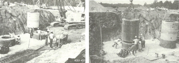
Figure 1: Models of Silo Headworks Being Readied for Test.
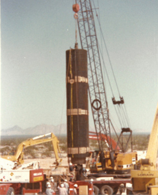
Figure 2: Launch Tube Being Emplaced for Test.
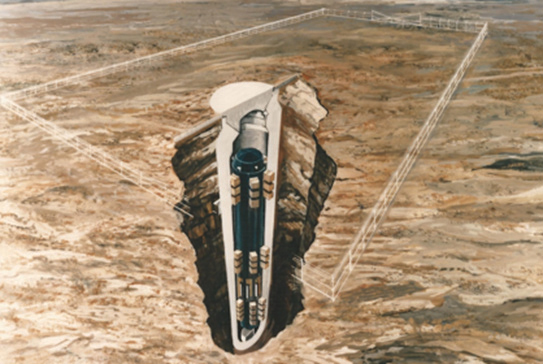
Figure 3: Artist’s Conception of Superhard Silo. 26 / dsiac.org Table of Contents WS
Cratering Effects
The size of a nuclear crater and associated ground motions also pose significant design challenges for superhardening. Theoretical predictions of crater formation did not agree with the HE data and the few large-yield nuclear tests in the Pacific. Theory has consistently indicated much smaller craters and ground motions, as well as a strong dependency of crater size on geology.
The Mini Jade “atmospheric” chamber test mentioned previously not only provided critical airblast data but also demonstrated a new capability for cratering experimentation. The chamber remained intact post-test, and measurements of the crater were in good agreement with analytical predictions. A subsequent chamber experiment (the Mill Yard underground test) was conducted with a different near-surface geology, and extensive ground motion measurements were obtained; these results also supported the analytical model. These findings motivated a two-year geophysical exploration of selected nuclear craters at the Pacific Proving Grounds (PPG) (the Pacific Enewetak Atoll Crater Exploration [PEACE] program) conducted by the U.S. Geological Survey, which has brought the empirical basis for yield scaling in line with theoretical expectations.
The PEACE Program
Peace Program Background
The two-year PEACE program was performed by the U.S. Geological Survey for DNA in 1984/85. It involved stratigraphic analysis and other geologic and geophysical studies in the vicinity of OAK and KOA craters and included underwater explorations [17].
The only experimental cratering data for strategic-scale, near-surface nuclear bursts are from the PPG tests, fired on or near coral atolls. Earlier interpretation of these data—based largely on photography, surface surveys, and lead-line measurements—gave these craters broad, saucer-shaped profiles (large aspect ratios) and large volumes. Extrapolated to continental geologies with the aid of calibration tests performed using HE, these data became the basis for the crater volumes in earlier editions of DNA’s authoritative Effects Manual-1 (EM-1).
These crater dimensions were much larger than those calculated in DNA’s Benchmark Cratering Program using first principles physical models in large computer codes (collectively referred to as BM-3); these acquired a high level of credibility as a result of extensive peer review. Portions of the models were also validated by comparison with data from underground nuclear tests and HE simulation tests.
Based partly on certain features of the OAK crater observed during earlier programs, the belief grew that the large volumes and aspect ratios of the PPG craters were due to geologic factors that were unlikely to be important to continental basing or targeting. The PEACE program was undertaken by DNA to more thoroughly characterize these craters, to provide a quantitative basis for understanding their development, and to determine the relevance of the PPG craters to strategic basing and targeting issues.
Figure 4 shows a comparison of the old EM-1 crater profiles for a 6-MT contact burst on dry soil over wet soil geology. Overpressures of 30,000 psi occur at the edge of the crater specified by the old EM-1; the same overpressures occur at more than twice the radius of the crater calculated by the BM-3 methodology.

Figure 4: Comparison of Old EM-1 and Theoretical (BM-3) Crater Dimensions.
The craters chosen for exploration during PEACE were OAK and KOA. The OAK crater resulted from a 9-Mt device fired on a barge anchored in 15 ft of water in the lagoon adjacent to the atoll island. Interpretation of both OAK and KOA is complicated by geological asymmetry (i.e., atoll reef on one side, lagoon on the other). The effect of the barge on source coupling further complicates OAK. The KOA crater resulted from a 1.4-Mt device fired on an atoll island. The KOA device was surrounded by a water tank, providing approximately 3 m of water tamping. This simplifies the modeling of source coupling physics; however, interpretation of the KOA crater is additionally complicated by the fact that several other large-yield devices had been previously fired close enough to KOA ground zero to have altered the properties of the coral in that region.
Despite the factor-of-six difference in yields, the apparent dimensions and profiles attributed to the OAK and KOA craters are similar, indicating that the energies that went into forming the craters in these events were about the same. This longstanding observation bears strongly on the rationale for developing weapons with enhanced coupling, such as shallow earth penetrators.
Conflicting Hypotheses
During the planning for PEACE, there were two principal and conflicting hypotheses to explain the large apparent volume and aspect ratios of OAK and KOA: (1) a small bowl-shaped, early-time crater, and (2) a large bowl-shaped, early-time crater.
- Small Bowl-Shaped, Early-Time Crater. In this hypothesis, the volume of the early-time crater was much smaller than the volume of the saucer-shaped apparent crater. The shape change (from bowl to saucer) was due to slumping of the transient crater walls and to subsidence of the surrounding wings (as illustrated in Figure 5).
A large increase in volume was associated with such post-event subsidence, which was presumed to have occurred under a large area of the sea floor. This subsidence was due to densification of the underlying coral, brought on by fracture of the weak, frangible skeletal structure of the highly porous coral. The hypothesis of a small early-time crater would indicate that energy coupling from contact bursts is inefficient, which is consistent with the BM-3 prediction methodology.
- Large Bowl-Shaped, Early-Time Crater. In this hypothesis, the volume of the early crater was comparable to the volume of the final apparent crater. The shape change was due to slumping of the crater walls and to converging flow of the surrounding region (a constant-volume process), as illustrated in Figure 6.
The large volume of the early-time crater was due either to more efficient source coupling than has been calculated by the BM-3 models or to weakness of the medium (e.g., due to transient liquefaction), which could lead to nearly hydrodynamic behavior during the formation of the crater.
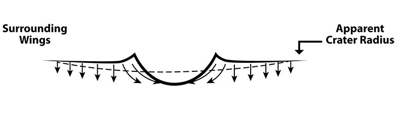
Figure 5 (top): Small Bowl-Shaped, Early-Time Crater.
Figure 6 (bottom): Large Bowl-Shaped, Early-Time Crater.
Key Observations
- Small Inner Craters. The sea floor profiles for both OAK and KOA consist of small central craters with distinct edges, surrounded by a depressed wing extending to the apparent radii. Abundant evidence of these small central craters was obtained from direct observations (scuba and research submarine surveys) and bathymetry, as well as from seismic surveys, downhole logging, and analysis of borehole samples.
- Similarities of OAK and KOA. The OAK-KOA similarities extend to the small central craters, the crater floor, and the “zone of sonic degradation,” though the craters differ in some of their subsurface geologic horizons. In terms of these effects, the energies coupled into ground motions from OAK (9 Mt on a barge) and KOA (1.4 Mt in a water tank) were about the same. This finding is important to theoretical results that indicate greatly enhanced energy coupling for shallow earth-penetrating weapons relative to contact bursts.
The depth of burst (DOB) equivalence of KOA can be estimated on the basis of the depth of water above and surrounding the device (3 m) or its equivalent mass of soil (1.5 m). Thus, KOA was at the equivalent of somewhat less than 1.4 m/Mt1/3 scaled DOB; horizontal confinement in the KOA tank was less than that which occurs in an actual DOB geometry.
- Long-Term Subsidence. An important discovery during the Marine Phase was the existence of a line of vertical steel rails on the depressed wing of KOA (i.e., within the apparent crater radius). These same rails appear on pretest drawings and photos as periodic supports for a long retaining wall that extended toward the KOA water tank. Today, they are still embedded in the beach rock, but they are under varying depths of water, extending inward to the edge of the small central crater. Another important marker (also seen in earlier surveys) is a concrete framework used to support one of the experiments at 1,830 ft from KOA. This frame was photographed before the event, a few days afterward, several months afterward, and again during PEACE. Before the test, it was a few feet above sea level, but its elevation in 1984 was several feet below sea level, with little or no horizontal displacement.
These rails and the concrete frame serve as Lagrangian markers showing late-time vertical subsidence on the wings of the crater. Further, comparison of bathymetric surveys made in 1958 (D + 58 days) and in 1984 show that the OAK crater floor dropped 20 to 40 ft in the central region and 5 to 10 ft on the surrounding wings between 1958 and 1984. Thus, 25 to 30% of 1984’s apparent crater volume in coral formed more than 2 months after the event. An appreciable but unmeasurable fraction of the apparent crater probably formed in the interval between a few minutes after the event and D + 58 days.
Peace Program Conclusions
The existence of the small inner craters affirmed the early-part of the small crater hypothesis that energy coupling from contact bursts of radiative sources is highly inefficient, as predicted by BM-3. The small central craters resulted from early-time excavation and flow processes. Soon thereafter, the unstable walls collapsed, or slumped, out to the presently observed central crater radii. Within these radii, strategic structures would experience severely disruptive environments involving large horizontal and vertical distortions and gradients. Outside of these radii, the distortional environments are much less severe, arising perhaps from flows, and in part from slower subsidence processes in saturated coral sand. This slow subsidence would not be present in dry alluvium.
The similarities of the OAK and KOA craters make it likely that the effective coupled energy from these bursts was essentially the same. Coupling from KOA was relatively uncomplicated, due to the tamping effect of the larger water mass surrounding the source. We therefore can be fairly confident of calculations showing that approximately 2.7% of the energy from KOA was effectively coupled into kinetic energy of downward-moving material.
CRATERING GROUND MOTION SIMULATOR
The nuclear chamber test is not suitable for testing silos, and HE cannot achieve nuclear source region pressures. The simulation approach adopted for large-scale testing is a sequential, three-stage process, incorporating crater and airblast effects. Termed the Crater and Related Effects Simulator (CARES), and illustrated schematically in Figure 7, this simulation consists of an HE subsurface charge that replicates the calculated pressure-velocity state at about the 50-kbar stage of the evolving nuclear crater, where subsequent pressures can be obtained with HE. (At this time, the crater has grown to about 5% of its final volume in a dry geology.) A sequentially detonated surface charge is used to simulate the airblast-coupled ground shock, transitioning into a conventional high-explosive simulation technique (HEST) bed to provide the primary airblast loading on the silo structure. Finally, in Stage 3, the ground motions measured in the CARES experiment is scaled up and reproduced in a large-size HEST-DIHEST (direct-induced HEST) configuration to provide a test bed for prototype silo structures.
Figure 7: Cross-Sectional View of CARES.
With reference to Figure 7, the first stage is represented by the underground “atmospheric” test, where agreement between predictions and observations of ground motion and final crater dimensions is presumed to substantiate the early-time, hydrodynamic phase of the theory. Stage 2 consists of an HE simulation of the crater, close-in ground motions, and airblast. Practical considerations limit this to kiloton-yield equivalence [18].
A fully instrumented CARES test replicating a 2-kt surface burst (1/8th scale for 1 Mt) provided the experimental rationale for establishing silo ground motion design criteria and designing large-scale HEST beds for silo validation testing. Figure 8 shows the CARES test bed under construction. Subsequently, a large-scale HEST test was conducted on a superhard silo that was full size for the SICBM or 5/8th-size for the Peacekeeper missile in which both airblast and direct ground motion effects were simulated.
Figure 8: CARES HE Simulator in Dry Alluvium at Yuma, AZ, Test Site (June 1985).
THE HARDENED MOBILE LAUNCHER
Overview
The survivability of the SICBM is achieved through a combination of hardness and mobility. The idea of hardening the mobile launcher against a massive barrage attack was born out of a desire to reduce the land area needed for its deployment. A hardness level of several tens of pounds/square inch of overpressure can reduce the deployment area significantly over that of an unhardened vehicle, and makes practical its deployment on selected military bases. Figure 9 shows the dependence of the number of attacking weapons needed to saturate the Hard Mobile Launcher (HML) deployment area for various levels of HML hardening. Hardening to levels of, say, 30 psi is no easy task, and it was fully appreciated from the outset that a radical vehicle design was required.
![Figure 9: Impact of Hardness on HML Deployment Area [13].](/wp-content/uploads/2019/11/ws-figure-9.jpg)
Figure 9: Impact of Hardness on HML Deployment Area [13].
The HML is hardened structurally against direct airblast effects. Sliding and overturning blast forces are reduced by aerodynamic streamlining of the vehicle and by exploiting the stabilizing effects of the vertical airblast forces. This concept is brand new and requires that the vehicle be deployed intimately with the ground so that no equilibrating airblast pressure acts on the underside of the vehicle. This innovation was radical, doing away with external restraints or tie-downs for the vehicle. While substantially simplifying the design, the change clearly demands a detailed understanding of the airblast flow field, including time phasing of the vertical and horizontal airblast components. A proof-of-principle experiment was conducted successfully in the Minor Scale HE field test. Figure 10 shows the functional modes of HML deployment.
Figure 10: Functional Stages of HML/SICBM Deployment.
The Air Force constructed two full-scale mobility test vehicles, one with wheels and one with tracks for mobility testing. Once a wheeled configuration was selected, mobility test and demonstrations were conducted with an engineering prototype vehicle, the Engineering Test Unit (ETU) [19, 20]. Figure 11 shows the HML ETU.
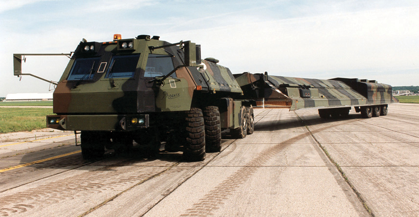
Figure 11: HML ETU.
Airblast Loading and Precursor Simulation
It is known from atmospheric testing experience that nuclear airblast waveforms and flow fields along the ground are dependent on the weapon’s height of burst (HOB) and thermal properties of the ground surface. The radiating fireball heats the ground ahead of the advancing shock wave, causing it to propagate more rapidly along the surface than in the (cooler) air above. This effect leads to radical changes in the airblast shock structure and, by entraining surface materials into the flow, vastly increases the aerodynamic drag forces on above-ground objects. There is direct evidence from prior atmospheric nuclear tests that these so-called thermally precursed flow effects can have a dramatic influence on the response of “drag-type” targets such as ground vehicles. (See Frankel et al. [21] for a useful summary of a broad range of nuclear weapons effects, including uncertainties.)
Numerical simulations of complex flows have matured substantially in recent years. Examples of these state-of-the-art capabilities are shown in Figures 12 and 13 (which are courtesy of Messrs. Allen Kuhl from the Lawrence Livermore National Laboratory [LLNL] and John Bell from the Lawrence Berkeley National Laboratory [LBNL]). The top row of images in Figure 12 is a numerical simulation of blast wave reflection from surfaces showing turbulent mixing in explosions over different surfaces. Directly below each image is a shadowgraph showing the respective shock structure from shock tube experiments [22]. Figure 13 shows the precursor shock structure and flow field from Operation Plumbbob, Priscilla Event (37-kt, 210-m HOB on 24 June 1958) using LLNL’s Adaptive Mesh Refinement (AMR) code [23].

Figure 12: Turbulent Mixing in Explosions.

Figure 13: Precursor Shock Structure, Operation Plumbbob, Event Priscilla.
DNA developed a novel method to simulate thermally precursed flow in the absence of a suitable thermal source. The underlying premise is that the flow develops as a consequence of the air shock propagating along the ground ahead of the main shock. While this effect is triggered in a nuclear burst by fireball preheating of the ground, it is not primarily a thermally dominated effect. Thus, it should be possible to replicate the flow in a layered, two-gas system of appropriately different sound speeds. This effect was accomplished at large scale under field conditions by confining a layer of helium gas along the ground under a thin Mylar membrane. The speed of propagation is controlled by the concentration of helium, which, in turn, is related to nuclear yield and HOB through theoretically based estimates of surface air temperature.
This approach was investigated by means of extensive numerical simulations and comparison with atmospheric nuclear data. It was tested in laboratory shock tubes at miniature scale and demonstrated successfully in HE field tests. Figure 14 shows the test setup in the Misty Picture event, an 8-kt nuclear equivalent HE source. A 0.5-mil-thick membrane measuring 400 ft wide x 900 ft long x 2 ft high contained helium at 95% concentration.
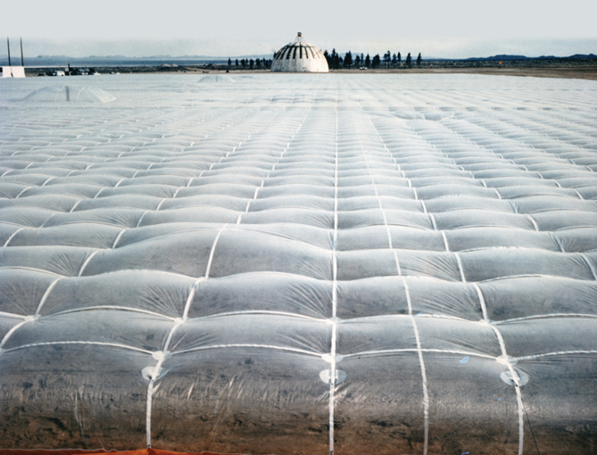
Figure 14: Misty Picture Test Bed Showing HE Source (in Background) and Mylar Helium Bag.
A test technique was qualified for hardness validation testing on this basis. One-fifth geometric scale models of two competing HML designs were tested in the Minor Scale event. This test was considered to be a successful proof-of-principle test for the HML design concept. Development of the SICBM and HML was terminated during the second Reagan administration, mostly for reasons of affordability.
THE FUTURE OF ICBM MODERNIZATION
Despite the remarkable technical achievements recounted herein, their impact on the U.S. nuclear posture has been essentially nil. In accordance with the Nuclear Posture Review (NPR) of April 2010, the Minuteman III Life Extension Program will continue with the aim of keeping the fleet in service to 2030, as mandated by Congress. The NPR notes that although a decision on any follow-on ICBM is not needed for several years, studies to inform that decision are needed now. Accordingly, the Air Force has completed an analysis of alternative deployment options, with the objective of defining a cost-effective approach that supports continued reductions in U.S. nuclear weapons while promoting stable deterrence.
This analysis of alternatives focuses on three options: (1) a “baseline” option that would extend the life of the Minuteman III through 2075, (2) a “replacement system “capitalizing on the existing Minuteman III silo infrastructure, and (3) a “hybrid” option that would mix the existing Minuteman III silo infrastructure with new road-mobile ICBMs.
To be sure, the Air Force also is modernizing the Minuteman missiles, replacing and upgrading their rocket motors, guidance systems, and other components so that they can remain in the force through 2030. The Air Force plans to replace the missiles with a new Ground-Based Strategic Deterrent (GBSD) around 2030 [24]. The Air Force released a request for proposals for the GBSD system at the end of July 2016 [25].
Meanwhile, the U.S. land-based ballistic missile force will consist of 440 Minuteman III ICBMs, each deployed with one warhead in existing Minuteman III silos. The Air Force has concluded that incremental modernization and sustainment of the current Minuteman III force is a cost-effective alternative to its replacement. Moreover, silo basing will likely continue to be the preferred option for the foreseeable future as the vulnerability of the Minuteman silos to a Russian preemptive strike is not nearly as much concern as it was during the Cold War [26]. That the “concern” and not the “vulnerability” is now reduced marks a major change in threat assessment and is the primary rationale for retaining silo basing.
In other words, the GBSD can be thought of as a “nuclear sponge” on a hair-trigger that would require some 500 attacking reentry vehicles (RVs) (or perhaps 1,000 from a reliability perspective) to successfully defeat in a preemptive strike. While a steep commitment of resources, the HML or covered trench would pose even a greater challenge to a potential attacker.
In conclusion, the problem of missile vulnerability has been defined away, not solved. As discussed by a report by the Defense Science Board [12] and Caston et al. [13], survivable basing solutions exist for both Peacekeeper and SICBM missiles, but their cost is probably two to three times the Minuteman upgrade cost. Clearly, a careful threat analysis is required as part of the GBSD design effort. It is further recommended that consideration of mobile basing take full advantage of the technology recounted in this article, including both the hardened mobile launcher and the covered trench.
Acknowledgments:
The author acknowledges the following colleagues for reviewing drafts and providing helpful suggestions for this article: Dr. Dan Burgess, Dr. Richard Cramond, Mr. Ken Kreyenhagen, Dr. Byron Ristvet, Dr. Jeff Thomsen, and Dr. George Ullrich. The author is also indebted to Dr. Reed Mosher and his staff for locating the superhard silo test photos in their archives. Finally, the author thanks the many distinguished engineers, scientists, and managers at the Air Force Ballistic Missiles Office, their supporting contractors, and supporting government laboratories.
References:
- Grier, Peter. “STRAT-X.” Air Force Magazine, January 2010.
- Medalia, Jonathan E. “Assessing the Options for Preserving ICBM Survivability.” Report No. 81-222F, 28 September 1981.
- Office of the Deputy Under Secretary of Defense for Research and Engineering (Strategic and Space Systems). “ICBM Basing Options: A Summary of Major Studies to Define a Survivable Basing Concept for ICBM.” December 1980.
- DeCarli, Paul S. “HUSSAR SWORD Series, HYBLA GOLD Event: Stress and Ablation Measurements.” POR 6973, SRI International, 1 February 1979.
- Office of Technology Assessment. MX Missile Basing. September 1981.
- President’s Commission on Strategic Forces (Scowcroft Report). “Report of the President’s Commission on Strategic Forces.” 6 April 1983.
- Reagan, Ronald. “Letter to Members of the House of Representatives on Production of the MX Missile.” 19 July 1983.
- U.S. General Accounting Office. “The MX Weapon System: Issues and Challenges.” Comptroller General Report to the Congress of the United States. 17 February 1981.
- Medalia, Jonathan E. “The MX Basing Debate: The Reagan Plan and Alternatives.” Issue Brief Number 1B81165, Library of Congress Congressional Research Service, 2 November 1981.
- U.S. General Accounting Office. “Small ICBM.” Report NSIAD-91-275, 30 September 1991.
- Medalia, Jonathan E. “MX Intercontinental Ballistic Missile Program.” Issue Brief Number IB77060, Library of Congress Congressional Research Service, Updated 14 December 1981.
- Office of the Under Secretary of Defense for Research and Engineering. “Small Intercontinental Ballistic Missile Modernization.” Defense Science Board Task Force Report, Washington, DC, March 1986.
- Caston, Lauren, et al. “The Future of the U.S. Intercontinental Ballistic Missile Force.” RAND Project Air Force, 2014.
- Pincus, Walter. “Weinberger Sets Up Panel to Criticize MX Missile Dense Basing.” Washington Post, 20 June 20 1982.
- Sevin, Eugene. “Validation Testing of Nuclear Survivable Systems.” 59th Shock and Vibration Symposium, Albuquerque, NM, 18 October 1988.
- Sevin, Eugene. “Superhard Facilities: Design & Test Concepts.” Defense Nuclear Agency, Washington, DC, 1985.
- Henry, Thomas W., and Bruce R. Wardlaw. “Enewetak Atoll and the PEACE Program: Geological and Geophysical Investigation of Enewetak Atoll, Republic of the Marshall Islands.” U.S. Geological Survey Professional Paper 1513-A, 1990.
- Cowler, M. S., et al. “DRY CARES Pre-Test Calculation of Cratering and Ground Motion.” DNA-TR-85-208, Defense Nuclear Agency, May 1985.
- ICBM Hard Mobile Launcher. https://www.youtube.com/watch?v=T80V5rbfZ6o, 9 January 2014.
- VirtualGlobetrotting. “Small ICBM Hard Mobile Launcher, Dayton, Ohio (OH).” http://virtualglobetrotting.com/map/small-icbm-hard-mobile-launcher/view…, 16 August 2007.
- Frankel, M., J. Scouras, and G. Ullrich. “The Uncertain Consequences of Nuclear Weapons Use.” The Johns Hopkins University Applied Physics Laboratory, 2015.
- Kuhl, A. L. “Validation of Numerical Simulations of Explosion Fields.” LLNL-TR-609492, Lawrence Livermore National Laboratory, 2013.
- Kuhl, A. L. “Turbulent Wall Jet in a Blast Wave Precursor.” 1993 Japanese National Symposium on Shock Wave Phenomena, edited by K. Takayama, Tohoku Print, Sendai, Japan (also published as UCRL-JC-112713), 1994.
- Woolf, Amy F. “U.S. Strategic Nuclear Forces: Background, Developments, and Issues.” Congressional Research Service, Report 7-5700, 10 March 2016.
- Insinna, Valerie. “Air Force Kicks Off Competitions for Two Critical Nuclear Programs.” Defense News, 29 July 2016.
- Caston, Lauren, et al. “The Future of the Intercontinental Ballistic Missile Force.” RAND Project Air Force Report, 2011.