

an email newsletter released every month highlighting the latest articles, events, technical inquires, and voices from the community
Computer-Aided Design (CAD) Systems for Satellite Assessments of Laser Effects Analysis

Posted on January 29, 2019 | Completed on January 31, 2019 | By: Matthew Perini, Patrick Buckley
What computer-aided design (CAD) systems do other U.S. Department of Defense (DoD) organizations use to set up target models (with material properties) that can be then imported to a physics-based simulation for further laser effects analysis?
Defense Systems Information Analysis Center (DSIAC) subject matter experts with extensive experience in the integration of computer-aided design (CAD) data for laser effects analysis supporting the Air Force Research Laboratory (AFRL) Directed Energy Directorate (RD) Laser Effects (LE) branch responded to an inquiry about current techniques used for geometry modeling in a laser effects lethality assessment. A summary of the current modeling techniques and recommendations for software or code development were documented and delivered to the inquirer.
1.0 TI Response
Patrick Buckley and Matthew Perini, who are subject matter experts (SMEs) at the SURVICE Engineering Company, assisted the Defense Systems Information Analysis Center (DSIAC) in responding to the inquiry. These SMEs have extensive experience in the integration of CAD data for laser effects analysis supporting the Air Force Research Laboratory (AFRL) Directed Energy Directorate Laser Effects (RDLE) branch, as they designed and maintain RDLE’s main software tool for high-energy laser weapon (HEL) lethality studies, “LaserFX” [1].
In SURVICE’s efforts supporting RDLE’s desire to improve the CAD-to-physics model workflow, the best successes have come from the use of commercial CAD software, such as SolidWorks, to develop the geometry data and then integrate material properties in the final custom format.
When a commercial CAD code is used, the CAD geometry must first be exported for use in an external application. All CAD codes provide several options for exporting geometry and other information associated with the geometry. SURVICE converts CAD files into the stereolithography (.STL) output for the LaserFX program developed for RDLE. STL objects are the triangular facets that form the surface of an object. The American Standard Code for Information Interchange (ASCII) version of an STL object is shown in Figure 1. Each solid object defined in the file is fenced by the keywords “solid” and “endsolid.” Within these key words, each triangle facet is defined by a facet normal and three vertex points. The vertex points are fenced by the keywords “outer loop” and “endloop.”
Note that other than an object’s name, the only information is the geometry of the object (i.e., no material type, color, or other descriptors are contained in the STL file).
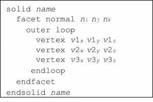
Figure 1: Example of an ASCII Version of an STL Object (Source: Matthew Perini and Patrick Buckley).
Because an STL file parser can be easy to write, the STL format is preferred over other more complicated export formats such as STandard for the Exchange of Product (STEP), Initial Graphics Exchange Specification (IGES), and other similar file types.
The inquirer referenced use of a purpose-built CAD program, eSMT, that allows the association of laser material types with geometry objects right inside the CAD program itself. It might be possible to add a user-defined list of materials to a commercial CAD code, which would give the user the ability to associate a laser material with a geometry object in the CAD code like eSMT. However, an exported format more complex than STL would be required if the material names are to be exported with the geometry.
SURVICE takes a different approach for the LaserFX code. Rather than wrestle with adding custom material lists to the CAD code (which would have to be done for each CAD code to be supported), a utility code called STLEdit was written. STLEdit performs the step of associating material types with geometry objects and, as its name implies, consumes STL geometry files. Figure 2 details a very simple example consisting of two rectangular parallelepipeds (RPPs). The RPPs were created in SolidWorks and exported from SolidWorks as two separate STL files. The STL files were then loaded into STLEdit, as the screenshot shows in Figure 2 [2].
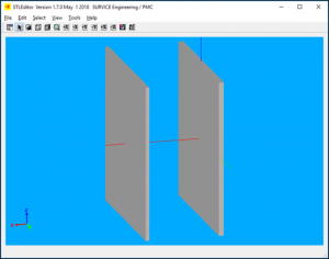
Figure 2: Screenshot From STLEditor (Source: Matthew Perini and Patrick Buckley).
The laser material association step is shown in Figures 3 and 4. Figure 3 is a properties table with one line per geometry object. Line two is “selected” in Figure 3, and its corresponding geometry object is colored red in the geometry display in Figure 4. From the materials list in the properties dialog, the user has selected “copperm2.dat” as the laser material code for the geometry object.
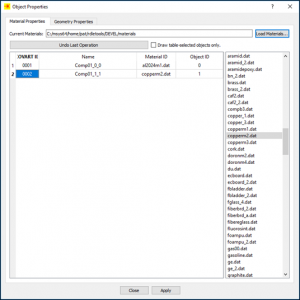
Figure 3: Properties Table (Source: Matthew Perini and Patrick Buckley).
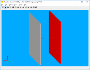
Figure 4: Screenshot From STLEdit of Material Properties Being Applied (Source: Matthew Perini and Patrick Buckley).
STLEdit exports the geometry objects in a simple triangle mesh format that also contains the laser material names. Figure 5 shows the STLEdit export file content for object 0002, with the laser material type “copperm2.dat.” There are other properties listed in the file that are not relevant to the current discussion. The RPP geometry is defined in “Vertex-Pool-Index-Set” format. As shown in Figure 5, the eight corner points of the RPP form the vertex pool and each triangle is then defined as a set of three indices into the vertex pool.
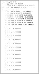
Figure 5: Example STLEdit Export File (Source: Matthew Perini and Patrick Buckley).
SURVICE refers to the geometry format shown in Figure 5 as a triangle “mesh” file, and it is what defines geometry for LaserFX. The inquirer’s “.nsm” format also contains the material name and the geometry definition. The “.nsm” CAD code does this within eSMT, while the SURVICE process is two steps:
- Export STL geometry from SolidWorks.
- Use STLEdit to associate laser material types with geometry objects.
It would therefore be recommended that the inquirer develop code or software like STLEdit to associate material properties to .STL files exported from commercial CAD software.
References
[1] AFRL/RDLE. “LaserFX User Manual,” draft.
[2] SURVICE Engineering Company, LLC. STLEdit Version 1.5.2 User Manual. December 2015.
Want to find out more about this topic?
Request a FREE Technical Inquiry!