


BACKGROUND
How well an air-to-air missile performs against a foreign target has long been of interest to military planners, designers, manufacturers, analysts, and operators. Early on, analysts used scale models and drawings to help them estimate the effectiveness of these missiles; but the computer revolution and continuous advancements in computation and visualization capabilities have made these estimates easier, faster, and more accurate than ever before.
In estimating the endgame effectiveness of air-to-air missiles, effectiveness is usually presented as the probability of damaging the target such that it is out of manned control in 30 s or less. Known as a K-kill, this probability minimizes the need to launch a second missile. K-kill also includes the more severe KK-kill (or sometimes a radar-recognizable kill), where the target breaks up immediately on warhead detonation. Another metric for air-to-air missile effectiveness (albeit less frequently used) is simply the ability to prevent the target from completing its mission. A practical problem in adopting this metric, however, is that the attacking aircraft may not be able to recognize a successful mission kill.
Many of the tools and techniques used to analyze air-to-air missile effectiveness are also used for aircraft survivability studies. That said, vulnerability studies are often extremely conservative, demanding damage levels that guarantee the quick defeat of the target. In contrast, survivability studies desire the aircraft to complete its mission if possible but definitely return to a friendly airfield.
Numerous computer programs (which are described in more detail in following text) are currently in use to evaluate missile effectiveness (both to investigate the design of new warheads and evaluate inventory warheads). These programs include the Advanced Joint Effectiveness Model (AJEM), TurboPk, Shazam, Endgame Manager, and Warhead Eval.
In their simplest application, these programs evaluate the effectiveness of a warhead at given burst points around the target. The burst points can be generated by a fuze model built into the effectiveness program or one that is external to it. Each of these programs has strengths, weaknesses, and proponents. All require the same basic information, a detailed knowledge of the target, the missile’s warhead, and the encounter conditions. However, the input formats for these programs vary, and considerable effort is often expended translating them from one format to another.
AIR-TO-AIR MISSILE TARGET DEFEAT MECHANISMS
An air-to-air missile can defeat an aircraft target in three ways: (1) via a direct hit of the threat missile on the target, (2) via blast from the missile’s detonating warhead, and (3) via the impact of fragments launched by the missile’s detonating warhead. A direct hit kill can occur if the intact missile impacts certain regions of the target or if, after detonation, the residual missile parts impact certain regions of the target. In a similar fashion, the target can be defeated by the warhead’s blast if, when the warhead detonates, it is within a specified distance of certain regions of the target. It is usually most efficient to determine if either of the first two mechanisms, direct hit or blast, defeat the target aircraft before evaluating the warhead’s fragmentation.
Figure 1 illustrates the regions of a typical aircraft deemed vulnerable to blast and direct hit kill. While these vulnerable regions are defined in terms of skin sections on the outside of the aircraft, it is understood that massive lethal damage is actually inflicted on the interior components beneath the skin. Some analysts might believe the regions designated as vulnerable to blast and direct hit are too conservative; however, the K-kill criterion requires the aircraft to fall out of manned control within 30 s. Many times, fighter-size aircraft have suffered extreme physical damage (such as shown in Figure 2), but continued to fly and eventually land.

Figure 1: Colored Surfaces Indicating Regions of
Example Aircraft Vulnerable to Blast and Direct Kills.

Figure 2: F-18 With Mid-Air Collision Damage.
The evaluation of the warhead fragmentation of an air-to-air missile appears to be rather straightforward— at least at first. The analyst first determines the encounter parameters of the missile’s exploding warhead relative to the target, then computes the trajectory of individual fragments generated by the exploding warhead and determines which fragments impact the target (as illustrated in Figure 3). Next, using fragment penetration equations, the analyst determines if those fragments could penetrate into the target through various internal parts and damage critical components. Finally, the overall effect of the damaged critical components on the fate of the target aircraft is evaluated through a Failure Analysis Logic Tree (FALT).

Figure 3: Tracing Fragments From Bursting Warhead to Target
The latest effectiveness codes can implement this approach directly while other, older codes, cannot. Designed at a time when computers were much slower, older codes compensate by using some form of precalculated vulnerability data. Nevertheless, the aforementioned evaluation sequence details the principal inputs required at some stage for all effectiveness calculations: a target model, warhead model, fragment penetration equations, component damage functions, and a FALT. These items may be used explicitly in the effectiveness code or may be used in the precalculations to prepare inputs for the effectiveness code.
TARGET DESCRIPTIONS
All of the effectiveness programs mentioned previously require a detailed physical description of the target. Depending on the effectiveness code, the detailed target description may be used directly by the code or used in preliminary calculations preparing inputs for the code. In contrast with survivability studies of U.S. aircraft, where vast amounts of vehicle descriptive data may be available, foreign aircraft data can vary from just a few photographs of a new aircraft to actual hardware of an older aircraft. For example, several Fulcrum and Flanker aircraft have been advertised online for sale in the United States for the past several years. Based on the descriptive data available, a computerized geometric model of the target aircraft (commonly referred to as a Target Geometric Model [TGM]), containing thousands of components, is constructed (as illustrated in Figure 4). Where detailed information is lacking, subject-matter experts use their knowledge of similar aircrafts to fill in the blanks.
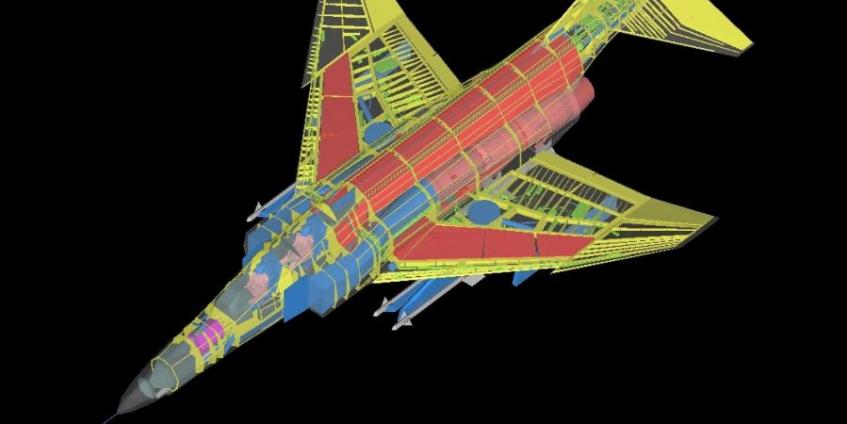
Figure 4: The Level of Detail in a Typical TGM
The earliest vulnerability studies used scale models and drawings to estimate the location, size of components, and their shielding. Then, in the early years of computerized vulnerability analysis, targets were modeled in SHOTGEN format. This format allowed objects to be meshed with triangles. It also allowed linear components to be modeled as straight lines. Later, aircraft geometric models were constructed in FASTGEN format, which added the ability to model objects as boxes, wedges, cylinders, spheres, and variations of each.
With the adoption of AJEM as the Joint Technical Coordinating Group for Munitions Effectiveness (JTCG/ ME) standard tool for vulnerability assessments, newer target models are constructed in BRL-CAD constructive solid geometry format or are constructed using SolidWorks, exported as STL files, and then converted to the desired format. Not surprisingly, convertibility has become an increasingly important feature in target modeling. Targets are first constructed in the specific format required by the analysis tool in use but quickly find use in other applications requiring a different format. Thus, tools are available to convert from almost any commonly used format to any other commonly used format.
In addition to modeling the geometry of the skin and internal components of the aircraft, the type of material and thickness for each component must also be specified to accurately predict the ability of fragments to penetrate the component. Vulnerability codes allow for a wide range of materials, including steel, aluminum, titanium, tantalum, tungsten, magnesium, and lead. Most components are not homogeneous but may be modeled as if they were. For example, a piece of avionics equipment may be modeled as a solid box of aluminum. To account for voids in the actual equipment, a density ratio is assigned to it. An avionics box may be assigned a density ratio of 35%. Thus, in the course of an analysis, a fragment’s computed straight-line path through the box would be reduced by 65%.
WARHEAD DESCRIPTIONS
The fragmentation characteristics of a warhead is usually obtained in testing by detonating the warhead at the center of a circular wall of fiberboard bundles that are thick enough to capture the fragments. After detonation, the location of each fragment is recorded, and the fragment is recovered and later weighed. Fragment speeds are determined by measuring their time of arrival after detonation at a known distance from the warhead detonation point. One popular technique is using high-speed video cameras to record the flash each fragment makes as it perforates a thin steel panel. Another popular technique is to use make-circuit screens instead of steel panels and record the time the fragment completes the electrical circuit when it perforates the screen. Figure 5 illustrates a typical arrangement of an arena test for a small warhead using both thin steel flash panels and make-circuit screens.

Figure 5: Typical Small Warhead Arena Test Setup
Almost all air-to-air missile warheads have cylindrical symmetry, thus simplifying the modeling of the warhead’s fragmentation pattern, which is described in terms of polar zones. The forward end of the warhead axis is defined to be at 0° while the normal to the axis is at 90°. The region between 0° and 90° is divided into polar zones of 5°. For each polar zone, the numbers, masses, and ejection speeds are specified. Generally, most analyses consider all the fragments originating from a point at the center of the warhead. This is a reasonable assumption if the warhead is several warhead lengths away from the target.
FRAGMENT PENETRATION
The earliest extensive investigation into the penetration abilities of steel fragments was conducted under an effort called Project Thor [1]. That project conducted firings of fragment masses from 5 to 825 grains at speeds as high as 12,000 ft/s at 10 different metallic materials. For each material, the test results were used to fit equations for residual speed and residual mass as functions of the impacting fragments mass and speed. Additional equations were developed for determining ballistic limit speeds as functions of fragment mass and target thickness. These fragment penetration equations have been used for many years in numerous vulnerability codes, such as the Computation of Vulnerable Areas and Repair Times (COVART).
In the 1980s, however, a need was recognized for an improved treatment of extremely high-speed steel fragments impacting aerial targets. The Thor mass loss equations did not predict the large decrease in residual mass when fragments shatter during high-speed impacts, thus spurring the development of the Fast Air Target Encounter Penetration Program (FATEPEN), which treats this issue and several others. Today, FATEPEN, which is the JTCG/ME-recommended penetration methodology for AJEM users, continues to be developed, adding more and more improvements and features.
COMPONENT DAMAGE FUNCTIONS
K-kill component damage functions specify the probability that a fragment, with a certain mass and speed, impacting the component will, within 30 s, prevent the component from functioning as intended. With few exceptions, analysts have little success predicting the time to failure. Therefore, requiring massive physical damage ensures the component cannot perform its intended function almost immediately. For example, a flight control tube that has 75% of its circumference cut may fail in less than 30 s or may function for more than 30 min.
“The Thor mass loss equations did not predict the large decrease in residual mass when fragments shatter during high-speed impacts.”
But a flight control tube that has 100% of its circumference cut has failed immediately. As mentioned, vulnerability criteria are often extremely conservative.
Ideally, component damage functions would be determined by firing various fragments at the actual component. Although this firing has been conducted for certain selected components, it is unfortunately neither practical nor affordable in most cases. Test firings are expensive, and, in the case of foreign aircraft, the components are rarely available. In lieu of this approach, vulnerability analysts approach the solution by viewing the component as a target itself. From available descriptive and functional information, the analysts infer what physical damage would defeat the component. Many times, it is decided that a perforation in some part of the case of the component will defeat the intended purpose of the component. The analyst can then, using penetrations, determine what masses and speeds are required to accomplish this perforation from various views of the component.
FALT
As defined previously, the FALT is a logical expression specifying the components and combinations of components that, if rendered inoperative, will result in a kill of the aircraft. The development of the FALT is preceded with a Failure Modes Effects and Critically Analysis (FMECA), which considers each component in the target and decides how its defeat will affect the aircraft. Some components may be redundant with other components, requiring two or more components being defeated before a K-kill is obtained. Of course, many components are not considered critical for K-kills.
Historically, most FALTS are constructed from a system view point (e.g., hydraulic system, fuel system, electrical system, etc.). A slightly different approach constructs the FALT from a functional approach. In this approach, the top-level FALT consists of the aircraft structure, propulsion, and directional control. The aircraft structure houses everything. It is not considered vulnerable to single fragments of the sizes used in air-to-air missiles. However, as discussed previously, selected portions of it are considered vulnerable to a direct hit by the missile body or to the blast produced by the detonation of the missile’s warhead.
Propulsion moves the aircraft through the sky, and directional control determines which way. Propulsion consists of one or more engines, which in turn require fuel. For twin-engine aircraft, K-kills require both engines to be defeated. In addition to providing propulsion, the engine-driven accessories provide hydraulic and electrical power. Directional control requires flight control surfaces and the means to move them. The means to move them requires a pilot, hydraulic power, mechanical linkages, and possibly flight control computers. Directional control is separated into pitch, roll, and yaw. Loss of pitch control leads to a K-kill, but loss of both roll and yaw control are frequently required for a K-kill. These top-level requirements are continually being expanded upon, ending with the individual components.
SPECIFIC EFFECTIVENESS CODES
The earliest computerized effectiveness programs did not trace the paths of individual fragments from the warhead to the target. Rather, they employed the vulnerable area concept and considered the expected number of fragments hitting the target. Warhead Eval, which is still in limited use, employs vulnerable areas. For a given fragment mass, speed, and attack direction, the vulnerable area of a component is the product of its presented area and its probability of being killed.
In the simplest case, the vulnerable areas for the individual critical components can be summed to a total target vulnerable area and considered as being located at the center of the target. These vulnerable areas can be precalculated using FASTGEN/COVART or AJEM. The effectiveness program determines the expected number of fragment hits on this total target vulnerable area. This approach has the advantage of calculation speed and can be adequate if the target is covered by the warhead’s fragment spray. It falters when the latter is not true, which can occur if the warhead is extremely close to the target or if the missile generally guides to a specific location on the target (e.g., a jet engine’s exhaust). In an attempt to compensate for this issue, rather than summing the vulnerable areas, the individual component vulnerable areas can be positioned at the component’s location.
The effectiveness codes Shazam and Endgame Manager trace the paths of individual fragments from the warhead to the target. Both codes rely on precalculated probability-of-kill (Pk) values determined for a range of fragment masses, speeds, and attack directions.
Shazam, the methodology used since the mid 1970s to evaluate the Advanced Medium-Range Air-to-Air Missile (AMRAAM), employs a model consisting of the target’s exterior and critical components but does not include the noncritical components. With few exceptions, the critical components are inside the target. The degradation of the mass and speed of fragments while traveling through the aircraft’s exterior and internal components (both critical and noncritical) is accounted for using precalculated tables. These tables are generated using COVART or AJEM and a target model that includes both critical and noncritical components. For a given mass, speed, and attack direction, these tables contain the average Pk for each of the critical components. Figure 6 illustrates the Pk values associated with each of the critical components for one set of these conditions. The Pk values, and thus the colors, change as the mass, speed, or attack direction changes.

Figure 6: K-Kill Critical Components Color Coded According to Their Pk Values for a Specific Fragment Mass, Speed, and Attack Direction.
The Pk Values and Colors Change as the Mass, Speed, or Attack Direction Changes
Endgame Manager, the effectiveness code used by the JTCG/ME, is similar to Shazam in that it also uses precalculated tables. The skin of the target is divided into tens or hundreds of panels. As illustrated in Figure 7, for each combination of fragment mass, speed, and attack direction, every panel has a Pk associated with it. This approach eliminates the internal components from Endgame Manager’s TGM. These Pk values are precalculated using the MSPK program, which performs a FASTGEN/COVART analysis on the complete TGM, skin, and all internal components.

Figure 7: Example of MSPK Output for a Specific Fragment Mass, Speed, and Attack Direction.
In Practice, the Skin Would Be Divided Into Tens to Hundreds of Components,
and the Pk Values and Color Would Change as the Mass, Speed, or Attack Direction Changes.
The TurboPk code, described in detail in the fall 2015 issue of the DSIAC Journal, is the latest effectiveness tool to implement the missile-target evaluation detailed at the beginning of this article. It is a fragment ray tracing code, self-contained and not requiring any separate vulnerability precalculations. The code was developed to take full advantage of the parallel processing possible with the multi-core central processing units incorporated into today’s personal computers. It operates with detailed geometric descriptions of targets using penetration equations, component damage functions, and FALTs in formats similar or identical to other effectiveness codes. The code also includes a warhead design tool.
CONCLUSION
To be sure, the rapid emergence and advancement of today’s inexpensive, fast personal computers have enabled the latest effectiveness codes to accomplish warhead design trade studies more quickly, more easily, and more effectively than ever before. The vital fragment ray traces that took so much time (and money) to accomplish just a few decades ago can now be generated, used, and discarded in just a few minutes. It should be noted, however, that if an older, well-established code continues to satisfy all the requirements, there may be no need to replace it, especially if an organization has a deep investment in it and changing to a newer code may require revisiting or rerunning many prior analyses.
References:
- The John Hopkins University. “The Resistance of Various Metallic Materials to Perforation by Steel Fragments; Empirical Relationships for Fragment Residual Velocity and Residual Weight.” Project Thor Technical Report No. 47, Baltimore, MD, April 1961.