


INTRODUCTION
Maintenance requirements for the rotorcraft fleet of the U.S. Army are sizable. Specifically, for the fiscal year 2016 budget, 35% of Army funds were spent on operations and maintenance costs while only 19% of Army funds were spent on procurement and research and development [1]. Some components are subject to a timebased maintenance (TBM) schedule that requires damage inspection at regular usage intervals. Battle damage assessment and repair (BDAR) is not the driving factor for maintenance. Instead, fatigue of vehicle components and erosion of rotor blade and engine components drive cost.
The significant resource requirement of TBM motivates the implementation of a maintenance-free operating period (MFOP). An MFOP is attractive because (1) the logistics tail that exists to supply vehicles in-the-field with replacement parts can be removed, eliminating the need for several forward positions to be kept for maintenance purposes; (2) the prognostics that enable confidence in the MFOP will reduce costs, labor, and downtimes and increase the mission availability; and (3) parts will only be replaced when they are unable to sustain a level of performance for an additional MFOP instead of replacement when damage of an arbitrary size is found.
Condition-based maintenance (CBM) [2–4] is a step toward the MFOP, where a measurable change correlated to some aspect of failure is targeted and tracked over time. CBM is similar to TBM in that tasks are performed at regular intervals, but action is taken only if failure onset is detected. Mechanisms of failure that are independent of the monitoring technique, however, will not be found, and the nucleation and propagation mechanisms of that damage are unidentified. For an MFOP to be viable, the structural state of critical components of the aircraft needs to be accurately monitored and precisely related to remaining useful life.
DAMAGE NUCLEATION, PROPAGATION, AND IDENTIFICATION
Damage nucleation occurs at submillimeter scales, often long before CBM can be detected. The nucleation event can be influenced by acoustic [5, 6] or electromagnetic [7–9] energy changes caused by grain boundary interactions, persistent slip band formation, fragmentation or rotation of grains, etc., until the damage propagates to a length scale [10–15] where it can be reliably tracked (Figure 1). At this point, the part would be replaced, although some part life remains. Once a phenomenon is identified, the nucleation-propagation behavior could be sensed by an automatic system perhaps embedded within the structure itself for reporting to a remote location. While tracking the damage state, the user can decide on adapting the vehicle operation either to maintain performance at a continual accumulation of damage or to decrease performance to sustain a longer operating life. The MFOP would then be the amount of time over which performance is maintained before a considerable amount of the component service life has been consumed and action must be taken to repair or replace the part.

Figure 1: Damage Progression and Performance vs. Component Service Life as It Pertains to MFOP.
Given that a detection of state is known, there are three possibilities for vehicles life compared to the MFOP:
- Vehicle needs mission adaptation to meet MFOP (e.g. maintenance, adaptive control laws, etc.).
- Vehicle will meet minimum performance objectives over MFOP.
- Vehicle has margin above performance objectives over MFOP.
Several works conducted by the U.S. Army Research Laboratory (ARL) have sought to link different monitoring techniques to the remaining useful life of composites and metal structures [16–19]. Composite specimen compliance, for example, has been shown to increase during fatigue testing. The resulting decrease in the stiffness over time for the data set can be modelled (labelled slope and intercept methods) to calculate the current remaining cycles for any specimen (Figure 2). Accuracy of the method is the difference between the vertical dashed line and the x-axis intercept. This method could be applied in cases where the compliance increase behavior has already been measured for a set of specimens and the load and displacement are being measured on the specimen of interest.


Figure 2: Remaining Useful Life Prediction vs.
Current Cycle Count Number Fatigued at 90%
Strength (a) and 70% Strength (b). Vertical
Dashed Line Represents Experimentally Measured Failure Cycles [16].
Measurements of small-scale damage have also been conducted in steel alloy 1095. A specimen tapered in width was tested in tension-tension fatigue to create a distribution of stress and thus life for a single applied load.
Tests were then conducted along the length to assess (a) nano-indentation response, which measures small-scale modulus and hardness behavior (Figure 4a); (b) X-ray diffraction response, which measures residual stress variation (Figure 4b); and (c) eddy current response, which measures magnetic permeability (Figure 4c/d). The experimental results from testing show changes in material properties, which can be tracked to remaining useful cycles.
The primary obstacle to developing these technologies from small scales to present relevance for aircraft structures is either minimization of the machines that conduct these experiments in the laboratory or development of sensors that detect the changes presented here and test their applicability at larger scales. Laboratory testing is practical for identifying what changes in the material should be investigated and what technology must be developed further to create the MFOP.
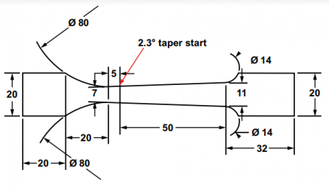
Figure 3: 1095 Steel Specimen Tapered in Width (in Millimeters) [17].

Figure 4: Technique Response as a Function of the Current Cycle (N) Over Failure Cycle Number (Nf) or Axial Location Along the Specimen [17].
TOPOLOGY OPTIMIZATION AND ADDITIVE MANUFACTURING
A structure may be designed more intelligently, adding, subtracting, or redistributing material volume for longer fatigue life by reducing stress levels. Topology optimization (TO) is an extremely powerful free-form rigorous design method developed around this ideology for designing structures [20] (Figure 5). TO can produce extremely complex yet efficient designs for prescribed objectives and constraints, which makes it ideal for use with additive manufacturing (AM). AM has the capacity to realize TO designs that are not possible by traditional manufacturing processes due to cost and tool-path constraints. Traditional TO formulations for lightweighting (i.e., without consideration of fatigue) often produce designs with stress concentrations or singularities that cause a reduction in fatigue life. As a result, manual adjustments or additional structural optimization is needed after the TO process to fulfill fatigue requirements. Therefore, research efforts are placed in developing and experimentally validating design methodologies that consider/couple fatigue within TO design for the lightweighting of structures.


Figure 5: Topologically Optimization for Given Boundary Conditions (a) and TO Solution (b).
AM processes are sometimes limited by feature size, locations of unsupported material known as overhangs, trapped material in hollow structures (analogous to voids), and material warping due to residual thermal stresses during manufacturing that result during cooling. TO design methodologies need to take into account the printing methods by which AM structures are made—in particular, TO design methodologies for considering overhangs and internal voids. Overhang areas require additional AM support material for the structure as the primary material is being built up while internal voids create stress concentrations and premature structural failures.
Several works seek to eliminate overhangs to produce self-supporting structures by limiting the printing angle, with respect to the vertical [21]. The resulting structure does not require extra support material for a solution of greater machinability to the boundary condition and loading conditions of the problem. Figure 6a represents a three dimensional TO solution for a cantilever beam. The converged solution contains an internal void, which could trap AM printing material. Research has been conducted to design for empty spaces instead of solid feature via void projection [22]. It can be seen in Figure 6b that this methodology results in a burrow from the top through the bottom of the beam, ensuring a path for material to escape. An application for this approach could be AM sandcasting where void space is filled with a sandslurry-like material, which acts as a place holder for future castings.


Figure 6: Cantilever Beam Topology Optimized Beam
With Overhang (a) and Internal Voids Topology
Optimized Beam With No Internal Voids (b).
Current TO design methodologies for maximizing structural stiffness do not give attention to the structure’s fatigue life, which can result in worse stresslife behavior.
Consider a simply supported beam in bending and the topology optimized solution in Figure 7. The objective of this optimization was a maximization of structure stiffness while keeping the structure’s volume lower than 50% of its original volume. The result was a doubling of the structural von Mises stress, which results in a considerable reduction in its fatigue life. Structural failure and fatigue properties must be considered for designs that are expected to be used in service. The reduction in structural fatigue life can be mitigated by first assessing the initial structure and then modifying fatigue constraints so that minimum performance is maintained while mass or volume is reduced.


Figure 7: Simply Supported Beam in Bending Beam Without
Topology Optimization (top) and Topology Optimized Beam (bottom).
In addition to maintaining fatigue life, it is believed that design solutions could also be used to improve fatigue life through use of multifunctional and self-sensing materials. TO designs considering fatigue life can be summarized as follows: (1) keep mass constant and change fatigue properties, or (2) keep fatigue properties constant and change mass [23]. Both objectives are of interest to the Army.
HIERARCHICAL AND MULTIFUNCTIONAL COMPOSITES
In addition to identifying and tracking damage progression, a structure may be designed with elements of toughening to resist specific failure mechanisms. Work at ARL has also designed nanotubecoated composite fibers to increase the bridging from one composite lamina to another. Such a structure resists delamination crack growth by creating a traction through-the-thickness across the interface. Wicks et al. achieved conformal coatings of radially aligned carbon nanotubes (CNTs) on the surface of alumina fibers, which exhibited enhanced interlaminar shear reinforcement [24]. Additional material systems of interest include ceramic fiber composites with a similar architecture with the goal of developing durable and damage-tolerant structural composites for mobile systems. Conformal coating of the ceramic fibers in CNTs gives rise to electrical conductivity via fluctuation induced tunneling. Composites made from these materials thus have the potential for a wide range of applications.
For example, when accumulating damage, composites have been shown to increase in resistivity [25], thus indicating that damage-sensing applications for such materials are within reach. The conductive tunneling also gives rise to heat generation with greater efficiency than traditional resistive heaters, resulting in composites that can be used for heating with minimal current [26]. If a suitable structural thermoplastic matrix material can be found, the heat generated by these low currents could be used to melt, and thereby heal, accumulated matrix damage. Novel copolymer blends can also provide multifunctionality through manipulation of hard- and soft-blocks for tunable elastic and dynamic behaviors for polyurethane and poly(urethane-urea). The integration of these technologies may one day lead to mobile systems with real-time material state awareness, with the ability to self-sense and self-heal damage prior to catastrophic failure. This ability would not only improve the operational effectiveness of the vehicle but also reduce maintenance cost and risk of failure.
Current TO design methodologies for maximizing structural stiffness do not give attention to the structure’s fatigue life, which can result in worse stress-life behavior.
CONCLUSIONS
The MFOP would save Department of Defense and Army resources that are currently dedicated to logistical sustainment of fleet vehicles. It would eliminate maintenance downtimes during the MFOP and increase Army readiness. However, there exist many challenges in developing fatigue damage nucleation-propagation understanding and techniques that are able to track the damage from the smallest possible scales and inform material state accurately. The decision-maker for the fleet should be given surety that performance can be maintained for the MFOP before action must be taken. The primary obstacle for transition from nano- or micrometer-scale testing to millimeter-scale measurement is developing measurement technologies from the laboratory to the field in the form of a compact and energy-efficient sensor.
TO research can be used to more intelligently design structures to have longer fatigue lives or be stronger given constant mass. Manipulation of AM with multifunctional, self-sensing, and hierarchical materials may increase the design space for longer part life given a specific mission as well. Careful consideration must be given to limitations of the technique in general, though with respect to overhangs and internal voids. Material development to design superior structures that are self-aware of their damage state, maintaining a minimum performance threshold, is a large step forward for the Army
References:
- Horlander, T. A. “United States Army FY 2017 Budget Overview.” http://www.defenseinnovationmarketplace. mil/resources/Army%20FY%202017%20Budget%20Overview.pdf, accessed 17 July 2017.
- Dieulle, L., C. Berenguer, A. Grall, and A. Roussignol. “Sequential Condition-Based Maintenance Scheduling for a Deteriorating System.” European Journal of Operational Research, vol. 150, no. 2, pp. 451–461, 2003.
- Jardine, A. K. S., D. M. Lin, and D. Banjevic. “A Review on Machinery Diagnostics and Prognostics Implementing Condition-Based Maintenance.” Mechanical Systems and Signal Processing, vol. 20, no. 7, pp. 1483–1510, 2006.
- Wang, W. “A Model to Determine the Optimal Critical Level and the Monitoring Intervals in Condition-Based Maintenance.” International Journal of Production Research, vol. 38, no. 6, pp. 1425–1436, 2000.
- Kube, C., and J. Turner. “Acoustic Nonlinearity Parameters for Transversely Isotropic Polycrystalline Materials.” Journal of the Acoustic Society of America, vol. 137, pp. 3272–3280, 2015.
- Lissenden, C. J., Y. Liu, and J. L. Rose. “Use of NonLinear Ultrasonic Guided Waves for Early Damage Detection.” Insight – Non-Destructive Testing and Condition Monitoring, vol. 57, no. 4, pp. 206–211, 2015.
- Chen, T., G.Y. Tian, A. Sophian, and P. W. Que. “Feature Extraction and Selection for Defect Classification of Pulsed Eddy Current NDT.” NDT&E International, vol. 41, no. 6, pp. 467–476, 2008.
- J. Garcia-Martin, J. Gomez-Gil, and E. Vazquez-Sanchez. “Non-Destructive Techniques Based on Eddy Current Testing.” Sensors, vol. 11, pp. 2525–2565, 2011.
- Nagy, P. B., and J. Hu. “Thermo-Electric Detection of Early Fatigue Damage in Metals.” Review of Progress in Quantitative Nondestructive Evaluation, pp. 1573–1580, 1998.
- Matlock, B. S., D. J. Snoha, and S.M. Grendahl. “Using XRD Elastic and Plastic Strain Data to Evaluate the Effectiveness of Different Cold-Working Techniques in Aerospace Materials.” Powder Diffraction, vol. 24, no. 2, S51–S58, 2009.
- Si, X. S., W. Wang., C. H. Hu, and D. H. Zhou. “Remaining Useful Life Estimation – A Review on the Statistical Data Driven Approaches.” European Journal of Operational Research, vol. 213, no. 1, pp. 1–14, 2011.
- Weiss, V., and A. Ghoshal. “On the Search for Optimal Damage Precursors.” Structural Health Monitoring, vol. 13, no. 6, pp. 601–608, 2014.
- Haile, M. A., A. J. Hall, J. H. Yoo, M. D. Coatney, and O. J. Myers. “Detection of Damage Precursors With Embedded Magnetostrictive Particles.” Journal of Intelligent Material Systems and Structures, vol. 27, no. 12, pp. 1567–1576, 2015.
- Curadelli, R. O., J. D. Riera, D. Ambrosini, and M. G. Amani. “Damage Detection by Means of Structural Damping Identification.” Engineering Structures, vol. 30, no. 12, pp. 3497–3504, 2008.
- Nevadunsky, J. J., J. J. Lucas, and M. J. Salkind. “Early Fatigue Damage Detection in Composite Materials.” Journal of Composite Materials, vol. 9, no. 4, pp. 394–408, 2009.
- Haynes, R. A., T. C. Henry, and D. P. Cole. “Interphase Mechanics in Fatigued Carbon Fiber Composite Materials.” 32nd Forum, American Society for Composites, 23–25 October 2017.
- Henry, T. C., R. A. Haynes, D. P. Cole, M. A. Haile, M. D. Coatney, and V. Weiss. “Tapered Test Specimen for Rapid Damage Precursor Identification.” Proceedings of the ASME Conference on Smart Materials, Adaptive Structures, and Intelligent Systems, 18–20 September 2017.
- Henry, T. C., D. P. Cole, F. Gardea, and R. A. Haynes. “Interphase Mechanics in Fatigued Carbon Fiber Composite Materials.” 75th Forum, Society for Experimental Mechanics, 12–15 June 2017.
- Cole, D. P., T. C. Henry, F. Gardea, and R. Haynes. “Damage Precursors in Individual Microfibers.” Proceedings of the ASME 2016 Conference on Smart Materials, Adaptive Structures, and Intelligent Systems, 28–30 September, 2016.
- Bendsøe, M. P., and O. Sigmund. Topology Optimization: Theory, Methods, and Applications. Berlin: Springer-Verlag, 2003.
- Gaynor, A.T., and J. K. Guest. “Topology Optimization Considering Overhang Constraints: Eliminating Sacrificial Support Material in Additive Manufacturing Through Design.” Structural and Multidisciplinary Optimization, vol. 54, no. 5, pp. 1157–1172, 2010.
- Guest, J. K. “Topology Optimization With Multiple Phase Projection.” Computer Methods in Applied Mechanics and Engineering, vol. 199, no. 1, pp. 123–135, 2009.
- Johnson, T. E. “Progress Toward Topology Optimization (TO) for Additive Manufacturing (AM) and Fatigue.” ARL-CR-0815, U.S. Army Research Laboratory, Aberdeen Proving Ground, MD, June 2017.
- Wicks, S. S., W. Wang, M. R. Williams, and B. L. Wardle. “Multi-Scale Interlaminar Fracture Mechanisms in Woven Composite Laminates Reinforced With Aligned Carbon Nanotubes.” Composite Science & Technology, vol. 100, pp. 128–135, 2014.
- Garcia, E., B. L. Wardle, A. Johnhart, and N. Yamamoto. “Fabrication and Multifunctional Properties of a Hybrid Laminate With Aligned Carbon Nanotubes Grown In Situ.” Composite Science & Technology, vol. 68, pp. 2034–2041, 2008.
- Yamamoto, N., R. Guzman de Villoria, and B. L. Wardle. Electrical and Thermal Property Enhancement of Fiber-Reinforced Polymer Laminate Composites Through Controlled Implementation of Multi-Walled Carbon Nanotubes.” Composite Science & Technology, vol. 72, pp. 2009–2015, 2012.