


INTRODUCTION
Active electronically steered array antennas are replacing conventional single-beam antennas in many of the new and emerging weapons systems. AESA antennas are not new, but their use is expanding because new technologies are enabling higher power, more compact implementations. This article describes the expanded test requirements for AESA antennas over single-beam antennas and describes a new test system approach. The new approach enables multiple simultaneous measurements, reduces test time, and enables closed-loop testing.
ANTENNA TESTING
Antennas may be tested individually or as part of a subsystem or system, such as a radar, jammer, or an aircraft. Tests are frequently conducted in anechoic chambers because they are more compact than outdoor ranges and the chamber eliminates interference with other radio frequency (RF)/microwave systems near the test facility. Tests are typically conducted to verify performance and may include measuring a variety of parameters such as power, signal fidelity, beam shape, beam polarization, beam pointing accuracy, and beam scan or switching rates.
Mechanically-steered, single-antenna, single beam systems do not normally require complex test setups. A few, or even a single test antenna (referred to as a probe horn), are mounted on a support or on the wall of the chamber. Scanning is performed by moving the antenna under test (AUT), which is mounted on a positioner. Rotation in azimuth and elevation can be performed either by the positioner or the beam-steering system of the AUT or some combination of the two. A typical test setup for a single antenna is illustrated in Figure 1.
![Figure 1: Typical Single-Antenna Test Chamber (Source: U.S. Naval Air Systems Command [NAVAIR]).](/wp-content/uploads/2019/11/mathis_fig_1.png)
CHALLENGES OF AESA ANTENNA TESTING
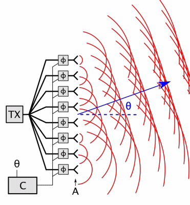
AESA antennas are fundamentally different from single-, mechanically-steered antennas. They consist of a two-dimensional (2-D) array of antenna elements and are controlled electronically by adjusting the phase differences between elements. The array structure can remain fixed, while the antenna beam can be steered electronically over a large range of angles. Multiple beams are produced by dividing the 2-D array of elements into subsets of elements or subarrays. Each subarray can be controlled independently of the other subarrays. Therefore, each of the subarrays can simultaneously point beams in different directions and radiate or receive different signals at different frequencies. Figure 2 illustrates a phased array operating in a single dimension, where the relative phase between each element of an array of individual antennas is adjusted to form and steer a beam in a particular direction.
Some of the key capabilities/test issues of AESA antennas can be summarized as follows:
- The antennas can produce multiple independent, simultaneous beams.
- The beams may be static or dynamic (stationary or sweeping in azimuth or elevation).
- Beams can also switch rapidly to different directions and between different polarization states.
- The increased number of degrees of freedom of a multibeam AESA system exponentially increases the number of test points. This increase, in turn, substantially increases test time, even with test automation.
- Closed-loop testing, in which the AUT is integrated with other systems in a hardware-in-the-loop simulation, produces dynamic, nondeterministic beam movement. This means that the specific direction that any beam will point during a test cannot be known prior to a test but must be determined in near real time.
AESA antennas also have some challenges (e.g., transmitting broadband signals at different angles). Since beam steering is based on phase and phase is frequency dependent, beam pointing is strictly narrowband. This means that the shape of broadband beams will vary as direction is changed—a phenomenon known as beam squint. It is also possible that broadband signals may be distorted at large angles. While it may be possible to partially compensate for this effect, this distortion does add to the test’s complexity. One question is how much modulation degradation is produced by a beam pointed far off boresight compared with the same modulation when the beam is pointed along boresight (i.e., normal to the plane of the antenna array). Another issue is isolation between subarrays. Will the modulation on one subarray affect the modulation on an adjacent subarray? If so, by how much? These and other issues add to the test’s complexity of AESA antennas.
AESA antennas have been a versatile and useful means of expanding the effectiveness of weapons systems. However, thorough testing of AESA antenna systems is more complex than systems with mechanically-steered, single-beam antennas. A complete characterization of system performance requires additional testing unique to AESA systems.
AESA antennas have been a versatile and useful means of expanding the effectiveness of weapons systems.
NEW AESA ANTENNA TEST APPROACH
Figure 3 illustrates the new test system approach. The beam or beams from the AESA antenna are detected using a 2-D array of probe horns mounted on the chamber wall. Individual probe horns are connected to an RF switch (not shown) by pairs of coaxial cables routed behind the absorber material on the chamber wall. Each beam can be received and tracked simultaneously with the other beams by switching the appropriate probe horns to the appropriate receivers.
The probe horn array is arranged in a square pattern. Other patterns can be envisioned, but any possible performance gain for a different pattern (e.g., a diamond pattern) is not sufficient to warrant additional complexity and cost. There is also a tradeoff between angular resolution and the number of probe horns; this tradeoff is affected by the frequency range for which the chamber was designed. For example, at lower frequencies, the beams are wider and fewer horns are required to intercept beams at any direction. At much higher frequencies, the beams are narrower, and more probe horns are required. An upper frequency range can be reached for which the beams are so narrow that they must be pointed near a probe horn to be received. The optimum arrangement of probe horns is determined by tradeoffs unique to each chamber.

This approach requires a fast, computer-controlled microwave switch. Each probe horn has two outputs to accommodate vertical and horizontal polarization; hence, each horn requires a pair of coaxial cables. The switch must be large enough to accommodate a pair of cables from each probe horn. The number of outputs depends on the number of simultaneous measurements required. More outputs drive up the switch’s cost.
MEASUREMENTS
Static Measurements
Static measurements, such as power, polarization, and signal fidelity, are the same for any antenna and do not normally require a large array of probe horns. In fact, static tests of a multibeam system could be performed with a single-probe horn by rotating the AUT so that each beam is sequentially pointed at the single-probe horn. Of course, this single-beam approach is much slower than a parallel approach. It is also possible to increase the number of fixed probe horns to accommodate multiple simultaneous fixed beams. This would enable multiple simultaneous static measurements in fixed directions.
Fixed Static Measurements
Fixed static measurements are not generally adequate for fully testing AESA antennas because of their dependence
on transmit angle. For example, a static measurement of signal fidelity at boresight must be repeated, with the beam pointed at other angles because of its dependence on angle. Again, such tests can be carried out with a single probe horn by rotating the AUT but with the substantially increased number of test points; the test time will increase accordingly. Fully testing an AESA antenna requires the ability to test each beam over its full range of directions. This measurement concept enables testing independent, multiple simultaneous beams.
Dynamic Measurements
Testing each beam over its full range of directions also enables dynamic measurements, such as beam switching time. Since AESA antennas can be electronically steered, they are typically capable of near-instantaneous switching between different directions. Further, each beam can function independently of, and simultaneously with, the other beams. This measurement approach enables multiple simultaneous dynamic measurements.
The most challenging example of dynamic measurements is when the AUT is controlled by external systems in other laboratories enabling remote or even closed-loop operations. In the case of a closed-loop operation, the beam direction is stochastic—its exact position in time cannot be predicted prior to the test. This measurement approach enables beam tracking during closed loop testing.
Beam Position Measurements
One of many tests for AESA antennas is to verify that the actual beam direction coincides with the expected direction. This new approach was initially motivated by a requirement to determine a beam direction without a prior estimate of the direction, and such a measurement is possible. However, in most test scenarios, an expected beam direction is known. Even with closed loop testing, an approximate expected direction or path can most likely be estimated.
Determining beam location is based on measuring the power at the four horns closest to the expected location. Then, a surface fit routine is used to find the actual beam location. The surface fit procedure requires knowing the beam shape at each probe horn and conducting a calibration procedure prior to testing in which the beam shape at each probe horn is measured and recorded.
Tracking a beam that is moving during testing is also possible. A series of position measurements are made, with the step size determined by the time it takes to compute a position. Each new position is estimated from the previous position and the expected path and slew rate. When the next measurement is made, the estimated position is updated. This iterative measurement-prediction approach is similar to that used in navigation applications of Kalman filtering. This process can be used to extend the operation to higher frequency beams not always visible to four adjacent probe horns.
Finally, with multiple simultaneous beams, overlapping beams are possible. When two beams are each pointed near the same probe horns and partially overlap, separately identifying the beams is necessary. In most cases, each beam will typically have a unique frequency, thus enabling band pass filtering during post processing to isolate them. However, if they have similar frequencies, modulation can be used to mix each beam to a unique intermediate frequency that can be separately filtered.
Since AESA antennas can be electronically steered, they are typically capable of near-instantaneous switching between different directions.
SUMMARY
AESA antennas are much more complex than single-beam mechanical antennas. For example, the angular dependence of their beam quality, with the potential for multiple simultaneous beams, leads to an exponentially increasing number of test points required to thoroughly characterize a system using an AESA antenna. The traditional single-probe horn approach of one measurement at a time can lead to an impossible length of time required for thorough testing.
The approach described here employs an array of probe horns covering an entire chamber wall. This enables parallel testing of multiple simultaneous beams, thereby substantially reducing test time. This approach also enables tracking a beam or beams at the wall during dynamic testing.