


INTRODUCTION
From the automotive diesel engine to on-board naval power generators to the aircraft jet engines, liquid atomization of hydrocarbon fuels is at the core of the energy generation and propulsion systems powering the vast majority of the Department of Defense (DoD) land-, air-, and sea-based platforms. As a result, in the foreseeable future, maintaining a critical technical superiority of the armed forces is virtually impossible without revolutionary advances in the design of combustion systems.
Combat aviation and terrestrial vehicles such as the Gray Eagle MQ-1C (shown in Figure 1) and the Joint Light Tactical Vehicle (JLTV) are powered by diesel engines running primarily on military JP-8 or F-24 fuels. Breakthroughs in engine technologies and fuel conversion efficiencies require a basic understanding of complex multiphase flow and combustion-relevant phenomena, including primary fuel/air mixture formation, particle-gas dynamics, and supercritical states. In liquid-fueled direct injection engines, the jet primary and secondary breakup processes have a significant influence on the fuel/air mixture formation and drop-size spatial distribution. A full understanding of the behavior is of significant interest for the design and operation of fuel injection nozzles and advanced combustors concepts. This understanding is also relevant in a broader scientific context for applications such as turbomachinery, material coating, additive manufacturing, fire suppression, etc.
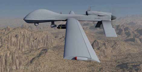
Figure 1: Rendered Army Gray Eagle MQ-1C Powered by a Turbocharged 160-hp Diesel Engine (Source: DoD).
Historically, the development of combustion systems proceeded through an empirical “trial-and-error” approach, without an in-depth understanding of all aspect of the underlying physics. One of the most common approaches is to avoid a detailed description of primary breakup in favor of a semiempirical model describing the sudden appearance of large droplets with specific momentum that then break up into finer droplets and vaporize. Such models rely on experimental data to set adjustable model parameters. This type of approach, while costly, still allows conventional engine designs to reach a remarkable level [1]. Fully predictive modeling is thus not possible at this time with these approaches.
However, with the recent advances in supercomputing power and numerical algorithms, first-principle simulations of the atomization processes are emerging today as a viable research tool to investigate fuel/air mixture formation in ever-more-extreme conditions and regimes that are far less understood and more difficult to diagnose experimentally [2–5]. Hence, high-fidelity numerical simulations can be used to probe the spray breakup dynamics and understand the behavior of an atomizing spray during stable operations and, more importantly, in off-design regimes (see Figure 2). Such insights often cannot be obtained through modern experimentation, and they are invaluable for guiding the development of stable, reliable systems, providing major savings in time and cost.
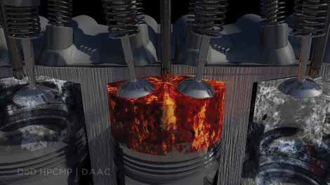
Figure 2: Conceptual Rendering of the In-Cylinder Atomization Process in a Diesel-Powered Army Gray Eagle UAV Engine (Source: DoD).
At the U.S. Army Research Laboratory (ARL), a multiyear research effort, in collaboration with industry (Cascade Technologies) and academia (Stanford University), is underway to support the development of Army propulsion systems. Inaugurated in FY15, the 5-year Frontier project is supported by the DoD High-Performance Computing Modernization Program (HPCMP) and the 6.1 base Vehicle Technology Directorate (VTD) program. The focus is on conducting research to address critical knowledge gaps in propulsion sciences, including combustion and complex multiphase flows. The project addresses issues relating to the nonreacting behavior of atomizing sprays, including the role of perturbation-driven instabilities on breakup and droplet formation, complex evaporation, and complex particle surface interactions. The major goal of this effort is the creation of a suite of breakthrough computational tools with the ability to predict the microscale flow physics of atomizing flows and moving interfaces using fundamental principles. The DoD will then be able to apply these models to the performance of any chemical-propulsion device that uses spray combustion, with the vetted models being particularly helpful in reducing the experimental steps necessary.
PHYSICAL DESCRIPTION OF PRIMARY ATOMIZATION
Liquid sprays involve a multiscale, turbulent physical process that presents several technical challenges. There is a liquid core (continuous) region that is disintegrated into fine sprays (dispersed phased) due to instabilities and aerodynamic interaction. Once the liquid core becomes unstable, it will favor the creation of ligaments that in turn will first create parent primary droplets, followed by secondary child droplets. Droplets are reduced in size due to evaporation, and combustion occurs while reduced droplets travel downstream of the injector nozzle. The resulting drop-size distribution or drop-velocities should be controlled to achieve the desired mass and heat transfer rates in most practical applications. Further, injector effects and needle wobble conditions are also important characteristics that have not been fully explored and strongly affect spray breakup.
Figure 3 shows the spray formation process. Points 1 and 2 in the figure show the ligament structure in the dense region, point 3 shows the onset of surface instabilities, and point 4 shows a characteristic outer ligament and droplet length-scales for this injector. Improved knowledge of primary breakup will lead to better predictions of spray characteristics, such as initial droplet size distribution, spray angle, and jet structure, thus enabling improvements in engine performance and control.
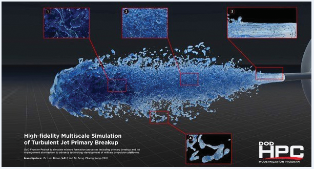
Figure 3: High-Resolution Visualization Using Ray Tracing of Spray Primary Breakup Phenomena From Diesel Injector (Source: DoD).
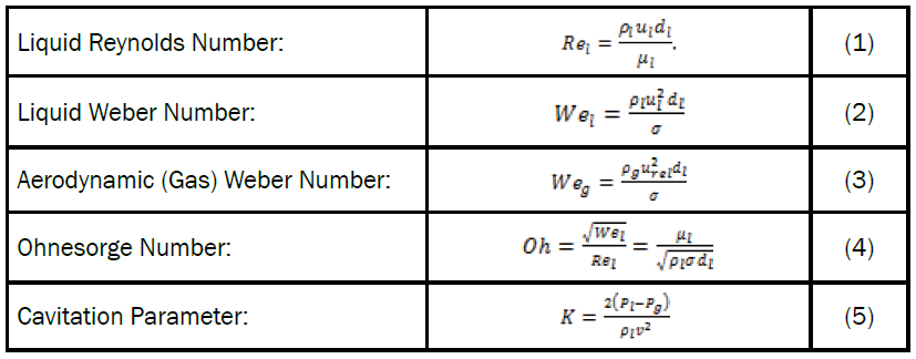
Table 1: Nondimensionless Parameters for Spray Classification
The characterization of spray behavior is better understood through the use of several nondimensionless parameters, as listed in Table 1. These parameters can be used to classify the spray into regimes that can, in turn, be used to predict its behavior. In primary breakup, the behavior of liquid sheets (or jets) can be classified into different atomization modes, depending on operating conditions. Figure 4 depicts the droplet breakup behavior with increasing Weber number conditions [6]. Earlier investigation of single fluid pressure atomization divided the breakup regimes of a circular liquid jet into three areas, depending on the liquid Reynolds number and the Ohnesorge number [7]. The regimes, which are illustrated in Figure 5, are further described as follows.

Figure 4: Turbulent Jet Breakup at (a) 6 gpm, (b) 7 gpm,
(c) 7.5 gpm, (d) 8 gpm, (e) 8.5 gpm, (f) 9 gpm,
(g) 9.5 gpm, and (h) 10 gpm. Corresponding Weg Ranges From 45.47 to 126.31 [6]
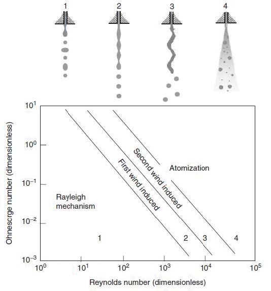
Figure 5: Primary Fragmentation Modes of a Liquid Jet in Pressurized Atomization [7].
- At low-Reynolds number, the jet disintegrates due to surface tension effects into fairly identical droplet sizes (Rayleigh regime, symmetric, or varicose instability).
- At intermediate-Reynolds number, drop formation is influenced by aerodynamics forces (nonaxisymmetric Rayleigh breakup). These forces cause symmetric (first wind-induced mode) and asymmetric (second wind-induced mode, asymmetric, or sinusoidal instability) wave growth of gas liquid interface that finally leads to jet disintegrations. This regime is known as the aerodynamic regime.
- At higher-Reynolds number, the jet disintegrates almost spontaneously at the nozzle exit. This regime is called the atomization regime.
Further, atomization can also be characterized by a jet breakup length where the fuel remains as a continuous medium. It is the distance from the nozzle exit to the breakup point, the general behavior of the breakup length, and its dependence on the jet velocity, as shown in Figure 6.
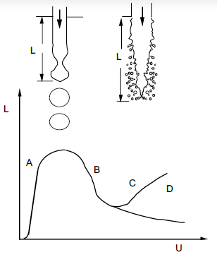
Figure 6: Liquid Jet Length (L) vs. Jet Exit Velocity (U) [8].
The initial part of the curve is described as the dripping region of the jet. The laminar flow region is located up to point A, where symmetric Rayleigh instabilities prevail. The upper point B indicates the transition from varicose to sinusoidal breakup mode. The breakup length decreases in the transition region B to C. When the fluid at the nozzle exit is already in a turbulent flow stage, and aerodynamic interaction between the liquid jet and the gas dominates the breakup, the jet breakup length increases with increasing velocity (from point C to D). The behavior of the liquid jet breakup length at jet velocities beyond point D is not uniquely defined yet, but, in general, tends to decrease [9].
RESEARCH MILESTONES
High-Speed Primary Atomization Simulations
The methodology for simulating spray primary breakup is based on the solution of the Navier Stokes Equations (NSE) coupled to a geometric unsplit interface-capturing method for immiscible fluids. The Volume of Fluid (VOF) method ensures discrete conservation of the volume fraction (F) by using nonoverlapping flux polyhedra for donor volumes. The approach also uses piecewise linear interface calculation (PLIC) representation to resolve the sharp liquid/vapor interface. For consistency (and stability), mass and momentum are convected using the geometric VOF method [2–4]. Further, the code is designed for the computations of unstructured meshbased methods on massively paralleldistributed architectures.
The fuel is delivered into the combustion chamber from a complex injector geometry that accounts for the minisac region (0.2 mm3), needle valve position, and a converging nozzle with a 90-μm orifice. To ensure a highfidelity model, the diesel injector was characterized via X-ray with a minimum resolution of 5 μm and integrated into the simulation environment. The fuel pressure is specified at 150 bar for a single-component n-dodecane fuel at a peak Reynolds, Weber, and Ohnesorge number of 9,204; 94,737; and 0.03, respectively, which sets the spray near the atomization regime. The physical properties were based on a fuel temperature at 298 K as an approximation to the water-cooled injector jacket temperature in the laboratory.
For reference, the fuel properties for n-dodecane employed are density ρ = 686 kg/m3, viscosity μ = 0.475 mPa.s, and surface tension σ = 18.6 mN/m. To specify diesel-type conditions, the chamber gas density is set to ρ = 22.8 kg/m3, by using 100% filled gaseous nitrogen at 303 K and a backpressure at 20 bar. The simulation initializes with a liquid-filled injector and prescribes a rate-of-injection profile with bulk inflow velocities based from reference measurements. A turbulent inflow generation condition is employed to help capture the transition to internal flow turbulence dynamics. The simulations provide detailed diagnostics in the optically dense region within 0 < x/d < 30 jet diameters.
In Figure 7, the mixture formation process of n-dodecane spray is presented to examine the effects of start of injection on the spray structure and emerging liquid topological structures. The detailed images show the evolution the transient spray injected into the quiescent chamber environment undergoing atomization. The jet is issued from the complex diesel injector with an experimentally prescribed mass flow rate. The issued spray is influenced by the rapid internal flow transients, and externally by the aerodynamic interactions through various fragmentation regimes. The formation of azimuthal surface instabilities is indicated by the Rayleigh-type behavior at the spray tip. The instability growthrate continues then forming crowns and ligaments that turn into the surrounding drops. Figure 7 shows various ligament structures at the periphery of the spray that grow, convect downstream, and break up into primary droplets.
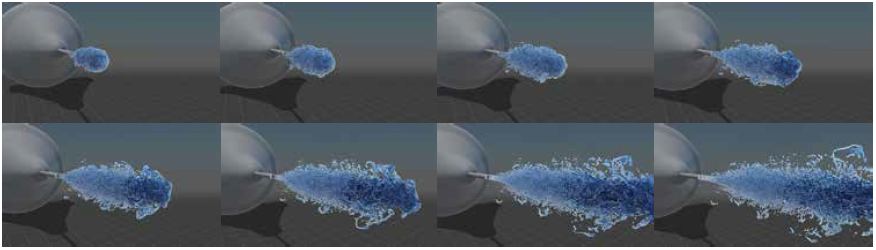
Figure 7: Transient Development of n-Dodecane Jet (150 bar) Showing Start-of-Injection Effects and Highlighting Ligament Formation and Breakup Process. Images From 0.11 to 0.18 ms at 0.01-ms Time Interval.
The numerical research has also revealed that the instability of the liquid jet is highly sensitive to velocity profiles and turbulence levels at the nozzle exit when the liquid jet transitions to turbulence. The sinuous breakup modes in the transitional flow were numerically confirmed, as observed in the experiment (Figure 8).
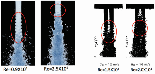
Figure 8: Sinous Mode Instabilities Confirmed Between Simulations (top) and Experiments (bottom) [10].
Further, an important 2016 research milestone involved the quantification via Direct Numerical Simulation (DNS) of the spray formation process using two jet-propellant fuels provided by the Federal Aviation Administration (FAA) National Jet Fuel Combustion Program. The model captured for the first time the complex liquid structures, including helical waves, ligaments, surface holes that lead to droplet generation, and turbulence interactions in an engine environment. The DNS study was validated against X-ray radiography measurements of spray density fields for two fuels, including an average properties jet-propellant (A2) and a highviscosity alternative jet fuel (C3). The high-viscosity C3 fuel showed improved atomization quality and faster penetration speeds by 5%. In addition, as shown in Figures 9 and 10, the penetration speeds and transverse fuel mass distributions are in good agreement with the experimental measurements from Argonne National Laboratory using X-ray radiography [11].

Figure 9: Liquid Jet Penetration for CAT A2 (Red) and C3 (Blue) Fuels With Experimental Measurements (Dotted Line).

Figure 10: Transverse Liquid Mass Density Distributions (micro-gram/mm2) on the
Projected Plane for Three Different Axial Positions From the Nozzle
(red=0.44 mm, green=1.0 mm, blue=2.0 mm) With the Experimental Measurements (Dotted Line):CAT A2 (top); CAT
C3 (bottom)
The computational expense of resolving all the critical length scales at large Weber numbers is prohibitively high, so the number of detailed numerical simulations conducted at realistic conditions has been limited. Note, a liquid jet moving at 100 m/s relative velocity with respect to the quiescent gas can generate droplets with diameters as small as a few micrometers. Predictions employing interface-capturing methods and discrete approaches are crucial for research purposes but have a high computational demand. To model the range of spatial scales present, spanning more than six orders of magnitude, requires computer codes that can exploit massively parallel architectures, as well as millions of CPU hours to describe the physics. Figure 11 shows the current scalability of ARL’s code (originally developed by Cascade Technologies) and its performance on ARL’s Excalibur HighPerformance Computing (HPC) system. The code is able to compute at 76% efficiency even at 1,500 controlvolumes/core and was tested at a maximum of 48,000 cores.

Figure 11: Scalability Study of Multiphase Weakly Compressible
Code With a Performance of 76% Efficiency With
1,500 Control-Volumes/Core; Maximum Test at 48,000 Cores.
Droplet Impingement Simulations
In simulating the physics of an impinging jet, a methodology based on smoothed particle hydrodynamics (SPH) is employed. In SPH, a field function (e.g., fluid property) is described by the integral representation method, which is reformulated based on the use of computational particles. The drop, surrounding gas, and the solid wall are discretized into free-moving and/or fixed particles. As a result, it becomes straightforward to track drop deformation and the interface of the liquid and gas. The governing equations to describe the fluid motion are discretized into the particle space, instead of the grid space that is used in conventional computational fluid dynamics. As a result, SPH has the advantage of reproducing drop deformation and incorporating the drop properties and wall conditions easily [12].
The numerical simulation of an impinging jet is accomplished by accurately predicting the details of dropwall interactions. In a diesel engine, the size of a typical fuel drop can be from 50 to 100 µm during wall impingement, with a velocity of approximately 50 to 100 m/s. It is anticipated that a drop will be discretized by a few thousand SPH particles. The size of a numerical SPH particle can be 2.5 to 5 µm in diameter, which is the resolution of the computational domain inside and surrounding the drop. At such a small scale, the liquid-gas interface can be resolved in detail. Moreover, the surrounding gas phase can also be resolved with high levels of detail, similar to those employed in typical DNS for flow simulation.
Figure 12 shows a sequence of predicted images during a drop impacting a liquid film. A series of diesel drops impacts the wet piston surface at a 45° angle. The initial drop diameter is 100 µm with a velocity of 50 m/s. The “red” liquid is the liquid originally contained in the drop; the “blue” liquid is the liquid originally in the wall film. We can see that the inner part of the crown is composed of the liquid from the drop. The leading drop impinges on the piston surface and creates a liquid film at a 45° angle. The subsequent drops impact the film, causing the film to spread and generate liquid ligaments and secondary droplets. These ligaments can further form droplets as time progresses. In a combustion engine, the gas flow will alter the trajectory of fuel drops, ligaments, and secondary droplets. The high-temperature gas and wall in the combustion chamber will also cause the liquid drops and wall films to vaporize and create combustible mixtures. These phenomena require further investigation by coupling the present numerical method with advanced physical models.
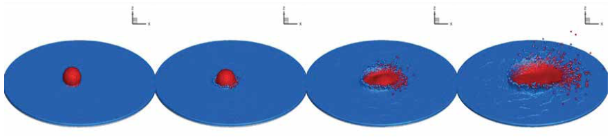
Figure 12: Typical Fuel Drop (Red) Impinging on Liquid Film (Blue) at a 45°Angle and Resulting in Crown Formation, Including Fuel Drops, Ligaments, and Secondary Droplets
Supercritical Sprays
As propulsion engine designs continue to push toward extreme conditions, the need for high-fidelity computer models that can describe transcritical to supercritical sprays is clearly needed. The nature of flows in a diesel injection process has motivated several recent studies to use the diffused interface method for the modeling of the injection sequence. In contrast to a sharp interface method, such as a volumeof-fluid method, where interfaces are explicitly tracked or resolved, the diffused interface method artificially diffuses the interfaces. This approach is particularly attractive for transcritical flows where interfaces are not present. However, it remains an open research question whether interfacial flows or droplets exist under conditions relevant to real applications [13]. Associated with the transcritical conditions are large thermodynamic gradients as the fluid undergoes mixing and possibly phase transitions. Accurately simulating these real-fluid environments remains a challenge. Here, a result from a diffused interface method is presented for the modeling of the fuel injection process under conditions relevant to high-pressure diesel engines. Compressible multispecies conservation equations are solved in conjunction with the PengRobinson state equation and real-fluid transport properties [14, 15].
In this study, a case denoted “Spray A” is considered, representing a benchmark target of the Engine Combustion Network. The single-hole diesel injection is operated with pure n-dodecane at a rail pressure of 1,500 bar. Liquid n-dodecane fuel is injected at 363 K through a nozzle with a diameter of 0.09 mm into a 900 K ambient environment at a pressure of 60 bar. The nonreacting case is considered, with the ambient gas consisting of pure nitrogen. At these conditions, the liquid n-dodecane undergoes a transcritical injection, where the liquid fuel is heated and mixes with the ambient gaseous environment. Fuel mass flux and temperature are prescribed at the injector nozzle using the timedependent rate of injection modeled using the virtual injection rate generator [16], recommended with default input parameters for the Spray A case (i.e., 1500-bar injection pressure, 60-bar back-pressure, 0.0894-mm outlet diameter, 0.90 discharge coefficient, 713.13-kg/m3 fuel density, and 1.50-ms injection time).
The liquid and vapor penetration lengths are extracted from the simulation results using a threshold value of 0.6 and 0.01, respectively, for the fuel mass fraction. The results up to 1 ms after injection are shown in Figure 13. The experimental vapor penetration length determined from Schlieren imaging and liquid penetration length from Mie scattering [17] are also shown for comparison. It can be seen that, for the vapor penetration, an excellent agreement with measurements is obtained.

Figure 13: Liquid and Vapor Penetration Lengths
Predicted in Comparison With Experimental Data [15].

Figure 14: Radial Profiles of Mean and rms Values of Mixture Fraction at Two Different Axial Locations
in Comparison With the Experimental Data Measured by Rayleigh Scattering [15].
The flow structures and mixing behaviors of the injection process further downstream are compared to the measurements of mixture fraction by Rayleigh scattering. Multiple injections in the experiments provide ensembleaveraged statistics. In the simulation, the statistics of the steady period of injection are obtained by temporally averaging between 0.6 ms and 1.2 ms after the injection. Figure 14 shows a comparison of the radial mixture fraction distribution at two different axial locations (x = 25, and 35 mm). As can be seen, there is a good agreement in the mean values of the mixture fraction at all three locations, while the simulation predicts slightly higher rms values compared to the experimental data. These results, along with the excellent agreement of the vapor penetration length as presented, show that the current numerical method is capable of predicting that the turbulent mixing process between fuel and the surrounding environment downstream of the injector after the dense liquid fuel is fully disintegrated.
Observed differences in the flow-field behavior near the injector require further investigations both numerically and experimentally.
FUTURE PERSPECTIVE AND NEEDS
In light of the previously described advancements being made in the Frontier project at ARL’s VTD, engine spray models have the opportunity to further enhance the capability to address existing technical knowledge gaps. Specific areas in which the models are expected and recommended to improve include the following:
- The ability to accurately describe the entire spray process, including the primary breakup dense, dilute region, and droplet-film region.
- The ability to describe the subgridscale models for multiphase flows and develop reduced models for the droplet formation process.
- The ability to couple molecular dynamics and continuum methods to improve the fidelity of equations of states for complex fluids and thermodynamics.
- The ability to capture the effects of injector nozzle turbulence and its mutual interaction with cavitation phenomena from first principles.
- The ability to describe the effects of an electrical field or charge, which is important for engineering-level electrostatic spray applications.
- The development of on-the-fly reduced-order models (lowdimensional manifolds) that can serve as surrogate models and be used for transition and concept design purposes.
- The ability to develop Uncertainty Quantification methods and tools for ensemble visualization to address wide variability in model physical properties.
Acknowledgments:
Financial support and computing resources for this work were provided by the DoD HPCMP Frontier project titled “Petascale High-Fidelity Simulation of Atomization and Spray/Wall Interactions at High Temperature and Pressure Conditions.” The author also gratefully acknowledges the support from VTD 6.1 Congressional project funds in propulsion research. Data analysis and visualization support is also acknowledged from Vu Tran, Rick Angelini, and Simon Su of the Data Analysis and Assessment Center.
References:
- Bravo, L., and C. B. Kweon. “A Review on Liquid Spray Models for Diesel Engine Computational Analysis.” ARL-TR-6932, U.S. Army Research Laboratory, Aberdeen Proving Ground, MD, 2014.
- Bravo, L. “High-Fidelity Simulations of Primary Breakup and Impinging Jet Atomization.” DSRC HPC Insights Magazine, pp. 3–8, November 2016.
- Bravo, L., D. Kim, F. Ham, and S. Su. “Computational Study of Atomization and Fuel Drop Size Distributions in High-Speed Primary Breakup.” Journal of Atomization and Sprays, 2017 (in press).
- Bravo, L., D. Kim, M. Tess, M. Kurman, F. Ham, and C. Kweon. “High Resolution Numerical Simulation of Primary Atomization in Diesel Sprays with Single Component Reference Fuels.” ILASS-Americas 27th Annual Conference on Liquid Atomization and Spray Systems, Rayleigh, NC, May 2015.
- Bravo, L., C. Ivey, D. Kim, and S. Bose. “High-Fidelity Simulation of Atomization in Diesel Engine Spray.” Proceedings of Center for Turbulence Research Summer Program, Stanford University, 2014.
- Ramalingam, S., M. D. Cloeter, B. Smith, S. C. Garrick, and W. Liu. “Experimental Investigation of Viscous Liquid Jet Transitions.” The Institute for Liquid Atomization and Spray Systems, North and South America, 25th Annual Conference on Liquid Atomization and Spray Systems, Pittsburgh, PA, May 2013.
- Reitz, R. D. “Mechanisms of Breakup of Round Liquid Jets.” Ph.D. thesis, Princeton University, Princeton, NJ, 1978.
- Lin, S. P., and R. D. Reitz. “Drop and Spray Formation From a Liquid Jet.” Annual Review of Fluid Mechanics, vol. 30, pp. 85–105, 1998.
- Ashgriz, N (ed.). Handbook of Atomization and Sprays: Theory and Applications. New York: Springer, 2011.
- Wu, P.-K., R. F. Miranda, and G. M. Faeth. “Effects of Initial Flow Conditions on Primary Breakup of Nonturbulent and Turbulent Liquid Jets.” AIAA 94-0561, American Institute of Aeronautics and Astronautics, Washington, DC, 1995.
- Bravo, L., D. Kim, F. Ham, K. Matusik, D. Duke, A. Kastengren, A. Swantek, and C. Powell. “Numerical Investigation of Liquid Jet Breakup and Droplet Statistics with Comparison to X-ray Radiography.” AIAA Joint Propulsion Conference, Salt Lake City, UT, 2016.
- Ray, M., S. C. Kong, L. Bravo, and C. Kweon. “HighFidelity Simulation of Drop Collision and-Vapor Liquid Equilibrium of Van Der Waals Fluids.” Proceedings of the Combustion Institute, vol. 36, no. 2, pp. 2385–2392, 2017.
- Yang., V. “Modeling of Supercritical Vaporization, Mixing, and Combustion Processes in Liquid-Fueled Propulsion Systems.” Proceedings of the Combustion Institute, vol. 28, no. 1, pp. 925–942, 2000.
- Ma, P., L. Bravo, and M. Ihme. “Supercritical and Transcritical Real-Fluid Mixing in Diesel Engine Applications.” Proceedings of Center for Turbulence Research Summer Program, Stanford University, 2014.
- Ma, P., M. Ihme, and L. Bravo. “Modeling and Simulation of Diesel Injection at Transcritical Conditions.” ILASS-Americas 29th Annual Conference on Liquid Atomization and Spray Systems, Atlanta, GA, May 2017.
- Pickett, L. M., and G. Bruneaux. “Engine Combustion Network.” Combustion Research Facility, Sandia National Laboratories, https://ecn.sandia.gov/, accessed August 2017.
- Pickett, L. M., S. Kook, and T. C. Williams. “Visualization of Diesel Spray Penetration, Cool-Flame, Ignition, High Temperature Combustion, and Soot Formation Using High Speed Imaging.” SAE International Journal of Engines, vol. 2, no. 1, pp. 439–459, 2009.