

, all-terrain vehicle, graphically modified (Source: U.S. Marine Corps).")
INTRODUCTION
The ability to manufacture at the point of need in austere environments is a very important concept for the military. Research at the U.S. Army Research Laboratory (ARL) shows that agile, expeditionary manufacturing could be accomplished using materials indigenous to the location of our operating bases. Indigenous materials include not only the organic and inorganic materials naturally occurring in the area, but also recycled materials from the operating bases (metals, polymers, etc.) and battlefield scrap. This idea could potentially reduce the huge logistics tail needed to conduct wars on foreign soil, saving valuable resources and lives and allowing the Warfighter to perform the mission instead of guarding and securing convoy transports. Having access to technology using locally available indigenous materials would benefit our Warfighters by improving operational readiness, decreasing transportation energy costs, reducing spares inventory needed in-theater, and increasing self-sustainability of our operating bases. This article will describe ARL’s efforts towards delivering manufacturing operations to the battlefield using indigenous recycled and reclaimed materials for feedstock.
BACKGROUND
Shrinking the logistics tail is an important benefit of utilizing materials in-theater [1]. The 2013 Army Sustainability Report outlines the Army’s desire to reduce the number of convoys required to resupply troops on the battlefield [2]. Reducing vulnerable convoys not only saves materiel and lives, but troops assigned to guard these convoys can be utilized for their intended purpose–engaging the enemy. The charter to reduce the tail in the combat zone is deemed critical to the success of the overall Army transformation, with relevance to Army future missions [3]. The Army’s research and development and sustainment communities should consider reducing the logistics footprint a principal goal. As stated in reference [4], “Technology will be one of the primary enablers to reduce the logistic footprint, and the reduction of the logistic footprint is clearly a key element of the future battlefield.” In addition, the armed forces are increasingly playing humanitarian roles in assisting citizens who have lost their assets in a natural disaster and/or live in parts of the world where there is no infrastructure for creating buildings, roads, bridges, or manufacture materials that can clean water, create energy, or repair machines. The ability to build and repair items with ingenious materials dually serves the armed forces’ and society’s needs.
GOAL
The goal of this study is to develop technology to use recycled, reclaimed, and/or scrap resources for in-theatre additive manufacturing to provide value-added products for the Warfighter. This article will briefly describe research being performed by ARL in the following areas: (1) produce additive manufacturing (AM) grade metal powder in a shipping container (intended to supply an operating base with feedstock for metal AM operations) and (2) utilize waste plastics for three-dimensional (3-D) printing applications.
The charter to reduce the tail in the combat zone is deemed critical to the success of the overall Army transformation.
CHALLENGES
There are many challenges associated with manufacturing indigenous materials in-theater. First, the materials must be readily available and in relatively large amounts to be useful. Next, a manufacturing process capability must exist at the operating base and be robust enough to provide a meaningful and reliable method of production, while retaining a small physical and environmental footprint. Scalability of these manufacturing processes must also be considered. In addition, power and energy requirements will dictate whether these manufacturing processes can be possible on the operating base. A further concern is how do extreme environments (i.e., vibration and thermal and atmospheric conditions) affect raw materials and what equipment is needed for the subsequent processing steps.
IMPACT
Transporting Army materiel to and from theatre is costly not only in terms of the logistic burden, but the time delays associated with replacing, repairing, and upgrading mission-critical equipment, systems, and vehicle platforms. The average Soldier alone generates up to 7-1/2 lbs of waste per day and often has very limited means to remove the waste; as a result, there is a need to address this from an environmental and health perspective. Water bottles are a major problem, representing 200–300 lbs/Soldier/year. Multiple waste streams composed of organic and inorganic materials (including trash from meals-ready-to-eat; cardboard boxes; cellophane and StyrofoamTM packing boxes; used oil and air filters; used motor oil; ammunition dunnage; empty brass cartridge casings; medical waste; used batteries; used steel-belted, off-road tires; etc. [5]) offer an opportunity for novel processing technologies to reuse these materials effectively in-theatre. Such an effort should be focused to offer a safe and environmentally responsible way to reduce disposal requirements by turning specific waste streams into value-added products.
ADDITIVE MANUFACTURING ON THE BATTLEFIELD
The Army has been using 3-D printers in forward areas in Afghanistan since 2012 [6]. These machines come in handy in producing parts made of plastic; however, no metal additive manufacturing equipment has currently made it to the battlefield due to various technical challenges. As Dr. Thomas Russell, former ARL Director, points out with respect to having the capability of having metal additive manufacturing in-theater [7], “Logistically there are benefits. One of our biggest challenges in the Army is that there is a huge logistics burden. If we could forward-deploy manufacturing capabilities, we would have the opportunity to manufacture parts in-theater, or repair parts. This is not just about manufacturing a new part, it’s often about how we can repair something that has been damaged. We have the opportunity to do that in-theater and use local materials. It’s an exciting area. I don’t think we’ve realized its full potential.”
Toward Production of Metal Powder on the Battlefield
One of the challenges associated with metal additive manufacturing on a forward-operating base (i.e., danger that needs to be reduced in risk) is transporting flammable metal powders for use with these processes. To counter this, ARL submitted a Small Business Innovative Research (SBIR) report titled, “Production of AM-Grade Metallic Powder on the Battlefield,” which was approved for Phase-I contracts. According to Strauss [8], the problem with traditional metal powder production in-theater (such as gas or water atomization) is that too much infrastructure would be needed, including the equipment, utilities (electric power, water, and inert gas), post-processing the powder, need for cleanliness, etc. Strauss concluded that it would be more practical to stock an inventory of alloy powder for anticipated needs. Although these are legitimate concerns, it was decided to move forward with the AM research to determine whether the operations could be optimized to reduce the burden of these hindrances.
The average Soldier alone generates up to 7-1/2 lbs of waste per day and often has very limited means to remove the waste.
Two companies were awarded a Phase-I contract—American Engineering and Manufacturing (AEM) teamed with the University of Ohio and MolyWorks Corporation. AEM proposed to use Lorenz force levitation and melting, and MolyWorks proposed to produce metallic powder in a mobile foundry. Although the companies were only expected to show a proof-of-concept in the Phase-I effort, MolyWorks used their existing mobile foundry to produce metallic powder, including AISI 4130 steel, titanium 6-4, copper (Cu-101), 316 stainless steel (Figure 1), and 6061 aluminum alloy (Figure 2). This mobile foundry is contained within an International Organization for Standardization (ISO) container. With further research and development, it is anticipated that the ancillary equipment (controller, power supply, gas supply, etc.) could all be contained in an ISO container. The process also needs to be optimized because only a small percentage of the powder currently made falls within the sweet-spot diameter for metal additive manufacturing (approximately -325 mesh/45-μm diameter). Within the mobile foundry, the metal is placed into the crucible, melted, and poured over flowing argon gas. The metal powder is formed and collected through vortex separation into the cyclones at the end of the equipment.

/wp-content/uploads/2019/11/manufacturing_pepi_fig2-494×494.jpg” alt=”Figure 2: The 6061 Aluminum Alloy Powder (-325 Mesh) Made in the MolyWorks Mobile Foundry Using Certified Alloy Starter Material (Source: ARL). ” width=”494″ height=”494″ />
Figure 2: The 6061 Aluminum Alloy Powder (-325 Mesh) Made in the MolyWorks Mobile Foundry Using Certified Alloy Starter Material (Source: ARL).
To determine the feasibility of using scrap in this process, ARL furnished MolyWorks with a piece of actual battlefield scrap steel and battlefield scrap aluminum to add to certified steel and aluminum, respectively. MolyWorks was also able to produce aluminum powder made solely from aluminum battlefield scrap (Figure 3). For the most part, the particles are spherical and contain some satellites.

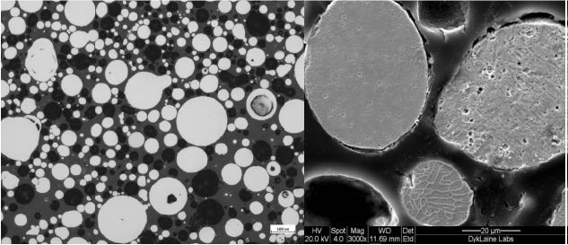
ARL also wanted to determine whether the powder produced in the mobile foundry could be used with the cold gas dynamic spray (cold spray) process. This is important because it would show that AM-grade metallic powder produced on the battlefield could potentially be used with a portable cold spray machine for repairing parts in-situ, extending the life cycle of these components, and reducing the logistics needed to get a spare part back to the theater of operations. The 316 stainless steel powder was placed within the powder feeder of the VRC Metal Systems Generation II (Gen II) portable cold spray system and sprayed onto 316L stainless steel substrate panels. For comparison, a sample of Praxair FE- 101 316 stainless steel powder was also cold sprayed onto a substrate. It took 35 passes to build up 0.10-inch of MolyWorks powder, as opposed to only 25 passes for the Praxair powder. In addition, the surface finish of the cold spray build using the MolyWorks powder was rougher than the Praxair powder (see Figure 4). To determine the reason for this difference, the panel was sectioned and metallographically prepared. Figure 5 shows a comparison of the cross sections of the two cold-sprayed powders. The MolyWorks powder appeared to have less porosity but more microcracks, indicative of higher residual forces within the build. This process would need to be optimized, but it did show that the powder could be cold sprayed with a portable unit. The Praxair powder was analyzed to determine how it compared to the MolyWorks powder. Figure 6 shows that the Praxair powder was water atomized, making “splat” shaped particles, vs. the spherical particles produced from gas atomization.


Particles of 316 stainless steel were mounted and polished and subjected to scanning electron microscopy. Figure 7 confirms that the powder produced by the mobile foundry is mostly spherical, with a smaller amount of spheroidal shapes and very few angular shapes. Some porosity is seen in the cross sections, likely a result of atomization gas becoming trapped in the molten particles during solidification. The microstructure appears to vary from particle to particle for the 316 stainless steel, perhaps due to variability in the manufacturing process.
The aluminum powder made entirely from aluminum battlefield scrap was also subjected to the cold gas dynamic spray (cold spray) process and deposited successfully, as shown in Figure 8. Three grooves were machined onto the test panels. Two grooves were filled with the portable cold spray system, and one was machined back to the level of the substrate. The cold spray deposition machined nicely, and no defects were visually noted. Figure 9 shows the mechanical mixing that was noted at the interface, indicating a strong adhesive bond.


Use of Indigenous Materials on the Battlefield
Historically, the Warfighter has used indigenous materials on the battlefield— from sticks and earth to form gabions and fascines, to sand and rock for sandbags, to expeditionary earth-filled protective-barriers and Hesco-barriers. According to MIL-PRF-32277 [9], this latter family of earth-filled barriers is intended to provide protection from visual detection, small arms fire, indirect fire, and perimeter intrusion. It should be noted that these products are more utilitarian in nature rather than technological innovations.
Three-Dimensional Printing of Casting Molds With Desert Sand
Three-dimensional printing with sand using commercial off-the-shelf printers is possible. However, these printers require original equipment manufacturer (OEM)-provided sand, as well as a binder, to keep the build together. The benefits of using 3-D printed sand molds vs. traditional sand molds include the following:
- Molds can be made in a shorter time, without complex and expensive tooling.
- Molds are generated from computer-aided design (CAD) models.
- Complex geometries can be accommodated, with faster design modifications.
In addition, the benefit of using indigenous sand means one less item would need to be shipped to the battlefield.
ARL teamed with the University of Northern Iowa (UNI) on a Defense Logistics Agency (DLA)-funded project to determine whether indigenous sand (such as that found in a desert or beach) could also be used with these machines with the appropriate binder to manufacture appropriate long lead time parts in-theater. The idea is 3-D print molds based on a CAD drawing of a part could subsequently be used to traditionally cast molten materials into the part. This process would yield a part that was not 3-D printed, so it may be more readily accepted by the end user. As a proof of concept, sand from the Defense Training Center at Fort Irwin, CA (Mojave Desert) was sent to UNI to research its potential use with a 3-D printer. The OEM sand that is typically used with these printers is silicon dioxide, shown in Figure 10. For comparison, Mojave Desert sand at the same magnification is shown in Figure 11. Noticeable differences exist, including size distribution (which can be countered through sieving), composition, and the fact that the OEM sand is washed (no dust). The OEM sand looks closer to beach sand than desert sand based on the lack of dust (see Figure 12 for comparison). A CAD drawing of a mock component (Figure 13) was utilized to determine if it could be cast in A356 aluminum using Mojave Desert sand. A mold was made using the OEM powder for comparison. UNI screened the material to eliminate oversize and undersize particles and bond strength tested the sand using conventional foundry resins. Because desert sands may contain materials that affect the curing of conventional resins, various chemical hardeners were investigated. Once the molds were 3-D printed with desert sand, the aluminum was poured and the parts allowed to cool. Figures 14 and 15 show the parts made with OEM and desert sand, respectively. The part made with desert sand appeared to have a rougher surface finish and would most likely need more post-processing than the part made with the OEM sand.

Figure 10: Typical OEM Sand Used With 3-D Sand Printers (Source: ARL).

Figure 11: Sand From the Defense Training Center, Fort Irwin, CA (Mojave Desert) (Source: ARL).

Figure 12: Sand From Clam Pass, Naples, FL. Aside From the Bits of Shells, etc., the Beach Sand Compares Favorably to the OEM Sand Used With 3-D Sand Printers (Source: ARL).

Figure 13: CAD Drawing of a Mock Component to Be Aluminum Cast Using 3-D Printed Sand Molds (Source: ARL).

Figure 14: Cast Aluminum A356 Part Using a 3-D Printed Mold With OEM Sand (Source: ARL).

Figure 15: Cast Aluminum A356 Part Using a 3-D Printed Mold With Mojave Desert Sand. Note What Appears to Be a Rougher Surface Compared to the Part Made With the OEM Sand (Figure 14) (Source: ARL).
Waste Plastics for 3-D Printing Applications
Although expeditionary AM is a relatively new area for the Army, the Army Rapid Equipping Force has already deployed polymeric AM fused deposition modeling (FDM) equipment to the battlefield as part of the Expeditionary Laboratory (ExLab) [10]. The ExLab contains a Stratasys Fortus 250, which is quite limited in the types of polymer feedstocks it can print, thus limiting applications. The main drawback of this machine is the requirement to use commercial filament from the OEM. Logical supply chain issues can again come into play if such filament is unavailable. Figure 16 shows some possible baseline parts made in the ExLab in-theater out of acrylonitrile butadiene styrene (ABS) polymer. Research at ARL was performed to determine the feasibility of 3-D printing using recycled polymers (from an operating base). This included FDM filament feedstocks of polyethylene terephthalate (PET) such as soda bottles; polypropylene (PP) such as yogurt containers; high-density polyethylene (HDPE) such as milk jugs; and polystyrene (PS) such as utensils. The challenges of using recycled materials include the purity of the materials, including additives/ fillers/dyes present in many plastic containers and biological and chemical contamination, mixed or unknown feedstocks, and limited power and cleaning materials availability for processing.
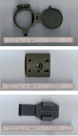
Figure 16: Photos of Items 3D Printed In-Theater (Courtesy of the Army Rapid Equipping Force) (Source: ARL).
Polymer filament was prepared by rinsing plastic containers with ethanol, drying and cutting into pieces that could be fed either through a cross-cutting paper shredder (PET, HDPE, and PP) or a high-speed blender (PS). After shredding, HDPE and PP were mixed in a high-speed blender to form uniform shred sizes. Shredded polymer was fed into a Filabot and/or Process 11 extruder at temperatures ranging from 140 °C to 270 °C to melt the polymers, and the extrudate was collected on a spooler (Filabot). Nozzle diameter was adjusted between 1.75 mm and 3 mm to account for die swell and shrinkage. Target diameter was 1.75 mm and 3 mm.
Filament was printed into tensile bars (Type V, ASTM D638 [11]) on FlashForge Creator Pro and Lulzbot Taz 6 FDM printers. Stereolithography (.stl) files were imported into Simplify 3D to generate toolpaths for the equipment to follow. This program converts the model file (.stl) into a series of toolpaths (.gcode) that the machine reads to determine where the print head moves and how much filament it extrudes. The bed temperature was varied between 60 °C and 100 °C, while the nozzle temperature varied between 220 °C and 280 °C. The build orientation was in the X direction, with the layer height set to 0.2 mm. The infill density, pattern, and outline overlap were optimized for tensile strength with the commercial Stratasys polycarbonate-acrylonitrile butadiene styrene (PC-ABS) filament.
Thermal properties were measured using differential scanning calorimetry (DSC) with a heat/cool/heat program (TA Instruments). All samples were heated at 20 °C/min to 300 °C, cooled 20 °C/ min to -50 °C, and then heated again at 20 °C/min to 300 °C. DSC data was processed using Universal Analysis software. Chemical analysis was performed by Fourier transform, infrared-attenuated total reflectance (FTIR-ATR) (Thermo Nicolet Nexus 870 ESP) using 256 averaged scans and 4 cm-1 resolution over a range of 4000 to 400 cm-1.
Select forward-operating bases have Stratasys FDM printing machines which typically use Stratasys PC-ABS filament. To determine the best mechanical properties that could be achieved with this filament, a series of tensile bars were printed in which the infill density, infill pattern, and outline overlap varied. Figure 17 displays the effect of infill density on tensile strength and stress-strain curves for 25%, 50%, 75%, and 100% infill (grid, 30% overlap). Surprisingly, there is little improvement in tensile strength above 50% infill. Tensile strength was higher for the 50% infill, compared to the 75% infill. Figure 18 displays SEM images of the fracture surfaces. All specimens show a printing defect between layers. Filament shape is partially distorted due to melting into the next layer, but filaments are still distinguishable. The breakage occurs for the 25% infill at the void (Figure 18A). There is some filament necking evident in the 50% infill specimen, and the 75% and 100% specimens also show signs of deformation. The effect of the infill pattern was also probed (50% infill, 30% overlap) using four common patterns—grid, fast honeycomb, full honeycomb, and triangular. Figure 19 displays the tensile results and a representative stress strain curve. There was little variation in tensile strength between the different patterns. The triangular and grid patterns had the most reproducibility, while the honeycomb patterns, particularly the fast honeycomb, had high margins of error.

Figure 17: Tensile Test Results on PC-ABS Tensile Bars With Varied Infill Density (A) Stress-Strain Curves and (B) Tensile Strength (Source: ARL).

Figure 18: Scanning Electron Microscope Images of Fractured PC-ABS Tensile Bars With Varied Infill Density (A) 25% Infill, (B) 50% Infill, (C) 75% Infill, and (D) 100% Infill (Source: ARL).

Figure 19: Tensile Test Results on PC-ABS Filament With Varied Infill Pattern (A) Stress-Strain Curves and (B) Tensile Strength (Source: ARL).
The outline overlap or percentage of overlap of adjacent filaments was also probed at 50% infill (grid pattern). Overlaps of 10% to 75% were probed; there was very little change between 30% and 75% overlap (see Figure 20).

Figure 20: Tensile Test Results on PC-ABS Filament With Varied Outline Overlap (A) Stress-Strain Curves and (B) Tensile Strength (Source: ARL).
Recycled polymers have a variety of different additives, fillers, and dyes and may have experienced different processing conditions, even for the same polymer type. To get a better understanding of different recycled polymer feedstocks and the best properties to expect from such materials, thermal and mechanical testing was performed. Tensile dogbones were cut out of milk jugs, soda bottles, yogurt containers, and plastic cups (polypropylene) using a die. Plastic water bottles could not be tested due to the ribs in the bottles. Polystyrene materials were too brittle to punch out. (Injection molded parts for all polymers will be compared in future work.) Representative stress-strain curves are displayed in Figure 21, along with the tensile strength and elastic modulus of each material. The soda bottles (PET) had the highest tensile strength, nearly 5x that of the polyolefin materials. The PET bottles had two yield points, with a significant amount of stretching before failure.

Figure 21: Tensile Test Results on Recycled Polymers (A) Stress-Strain Curves of Die-Cut Tensile Bars and (B) Tensile Strength and Modulus (Source: ARL).
Table 1 displays thermal properties from DSC measurements. The two sources of PP examined, PP cups and yogurt containers, have the same melting temperature and similar percentages of crystallinity. However, the crystallization temperatures are 16º apart. This difference may be from the dyes and fillers in the yogurt container compared to the transparent cups and likely had less additives. The thermal characterization of PS only provided glass transition (Tg) information since it is an amorphous polymer, and the Tg’s were identical for the two sources of PS. The thermal information for the PET water and soda bottles was markedly different. The PET in the soda bottles had a higher Tg, melting point, and lower crystallization temperature and was more crystalline. Only one source of HDPE was examined.
Table 1: Thermal Characterization of Recycled Polymers Using Differential Scanning Calorimetry (Source: ARL).

Chemical characterization was performed using FTIR (Figure 22). The two sources of PS examined (petri dishes and utensils [opaque]) appear chemically identical, even with the presence of fillers in the utensil. The two sources of PET (water and soda bottles) also appear identical. The PP cups and yogurt containers had three regions that were notably different, most likely due to the dyes in the yogurt containers.

Figure 22: Chemical Characterization of Recycled Polymers Using FTIR-ATR. Yellow Boxes Highlight Different Peaks Between Polypropylene Sources (Source: ARL).
Recycled PS, PET, and PP has been fabricated into filament and printed into tensile bars. Tensile bars from recycled plastic were printed using either 50% (PS) or 100% (PP, PET) infill, with a grid pattern and 30% overlap. The PS tensile bars were quite brittle and had a mean tensile strength of 19.9 ± 3.9 MPa or about half of the Stratasys filament (34.0 ± 0.8 MPa). Because the PS filament was so brittle and difficult to spool and feed in the printer, infill and printing parameters were not optimized. PET filament from plastic soda bottles had a tensile strength comparable to the Stratasys PC-ABS filament (36.4 ± 3.1 MPa [PET] vs. 34.8 ± 0.8 MPa [PC-ABS]). PP from yogurt containers had a lower mean tensile strength of 20.1± 2.3 MPa. Printing parameters are currently being optimized to improve tensile strength of the printed parts from recycled filament. Filament has been made with HDPE but not yet printed or tested.
CONCLUSIONS
Reducing the dependence on the logistical supply chain on forward-operating bases will not only increase operational readiness and the self-sustainability of Warfighters in-theater, but also improve the safety of the Warfighter by reducing threat vulnerabilities. The ability to fabricate needed parts on demand, in-theatre in austere environments with available resources, would be game-changing for the military.
With the production of AM-grade metallic powder in-theater, MolyWorks has made great strides in producing powder in a mobile foundry contained within an ISO container. The batches can be made with scrap metal, and the subsequent powder can be cold sprayed and additively manufactured using the Laser Engineered Net Shape (LENS) process. The vision is to have the future capability to produce this powder in-theater for real-time repair of components (e.g., with cold-spray technology) or building spare parts.
UNI has shown that desert sand can be 3-D printed to make casting molds to produce parts via traditional foundry casting. This proof-of-concept showed that locally available sands, with little processing, could be effectively utilized to produce metal casting molds of sufficient strength to cast light metal alloys. This capability may someday allow manufacturing parts in-theater using indigenous sand and recycled/ reclaimed battlefield scrap.
The ability to fabricate needed parts on demand, in-theatre in austere environments with available resources, would be game-changing for the military.
Finally, ARL researched using recycled plastics with 3-D printing applications. Studies were conducted to determine the best print parameters to make the strongest part with the least amount of material. Sources of potential plastic waste were characterized to understand thermal, mechanical, and chemical properties. PET had the highest tensile strength—likely, the best candidate for making strong plastic parts. Tensile bars were printed with recycled filaments and tested. Future work will involve testing tensile specimens from recycled PP, HDPE, and PET filaments.
FUTURE WORK
ARL is interested in all manufacturing processes that can be utilized in-theater with indigenous recycled and reclaimed materials and will pursue paths leading to the ultimate use of AM on the battlefield using these materials as feedstocks.
The authors wish to thank the following individuals for their contributions to this work: Chris Eonta and team at MolyWorks Corp.; John Lawmon and team from AEM, Inc. (AM-Grade metallic powder from battlefield scrap); Prof. Jerry Thiel and team from UNI; and Kelly Morris and team from DLA (3-D printing with desert sand for metal casting).
References:
- Col Genaro J. Dellarocco. “Force Projection Research and Development: The Key Enabler for Army Transformation.” Army War College, 10 April 2001.
- Tan, M. “US Army Outlines Push to Save Resources, Lives.” Defense News, vol. 27, no. 44, p. 14, November 2012.
- Col Larry W. Jameson. “Shrinking the Logistics Tail in the Combat Zone.” Army War College, 9 April 2002.
- LTC Darrell S. Ransom. “Logistics Transformation – Reducing the Logistics Footprint.” Army War College, 5 April 2002.
- CPT Terry Wilkin. Personal conversation, U.S. Army Research Laboratory, Aberdeen Proving Ground, MD, 12 August 2014.
- Cox, M. “Army Sees Rapid Prototyping as Key to Rapid Innovation.” Military.com/Defense Tech, 1 April 2015.
- “Dr. Thomas Russell: Research Vision for 3-D Printing.” Army Technology Magazine, RDECOM Public Affairs, 05 July 2014.
- Strauss, J. “Feasibility Study on the Deployment of an Atomization System Contained Within Conex Shipping Containers to Operate at a Forward Operating Base.” Special Report, U.S. Army Research Laboratory, Aberdeen Proving Ground, MD, 25 November 2015.
- U.S. Army Research Laboratory. Performance Specification – Expeditionary Earth-Filled Protective Barriers. MIL-PRF-32277, Aberdeen Proving Ground, MD, 30 July 2010.
- Cox, Matthew. “Mobile Labs Build on the Spot Combat Solutions.” http://www.military.com/daily-news/2012/08/17/mobile-labs-build-on-the-s…, accessed 30 January 2017.
- ASTM D638. “Standard Test Method for Tensile Properties of Plastics.” ASTM International, West Conshohocken, PA, 15 December 2014.