


INTRODUCTION
The future battlefield will be highly complex and congested. The electromagnetic (EM) environment will consist of a complicated mix of signals, both threats and friendlies. Figure 1 is a simplified illustration of some of the potential players. Passive coherent location (PCL) radars represent an emerging threat that differs from typical radar threats in that no radar signal is transmitted. Rather, the radar signals consist of signals of opportunity, such as radio or TV stations, enabling PCL radars to operate covertly. In other words, they can actively track targets of interest without alerting the target to their presence.
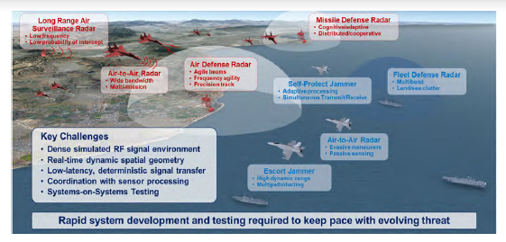
Figure 1: Contested Environment Illustration (Source: NAWCWD).
The Electronic Warfare Integrated Laboratories (EWIL) at the U.S. Naval Air Warfare Center Weapons Division (NAWCWD) provides a simulation of contested environments enabling the testing of new and emerging systems against realistic threats and threat scenarios. A key element of this test environment is the Testing Theater Operations Using Real-time Networks Achieving Multiple Interconnected Nodal Tactics (T2OURNAMINT) system, which serves as the hub of a digital electronic warfare (EW) environment. Adding a PCL radar to the T2OURNAMINT test environment will enable the development of countermeasures to this unique, emerging PCL radar threat.
PCL RADAR OVERVIEW
PCL radars are a variation of bistatic radars, which are radars in which the transmitter and receiver are not colocated. This is in contrast to the more common monostatic radars having a transmitter that is colocated with or near the receiver. The unique feature of PCL radars is their use of signals of opportunity.
Signals of opportunity can be radio or TV broadcasts, including both analog and digital TV, mobile telephone networks, local area networks, and even satellite transmissions. The most common transmitters used in existing PCL systems are FM radio stations. They are available worldwide, and the signal bandwidth (50–100 kHz) and power (typically, 100–250 kW) are adequate. Digital TV signals are also commonly used in areas where they are available.
Figure 2 illustrates the elements of a PCL radar, where Rt is the transmitter-to-target distance and Rr is the target-to-receiver distance. The direct path distance from the transmitter to the receiver can vary from a few kilometers to 100 km. The location of each transmitter and its distance to the receiver are known by the receiver, which must have a separate, dedicated receive channel for each transmitter.

Figure 2: Key Elements in a PCL Radar (Source: NAWCWD).
The PCL receiver detects a target by first collecting and digitizing a sample of the direct path transmission. The sample is then used to form a matched filter, which the receiver uses to search for the same signal reflected from targets of interest. The peak of a matched filter response is used to determine the differential time between the two paths. Since the transmitter position is known, the propagation time from the transmitter to the target to the receiver can be computed. Knowing this time delay enables the computation of an ellipsoid with foci at the known transmitter and receiver positions. The target is located on the ellipsoid surface. Finally, the intersection point of at least three such ellipsoids locates the target in three dimensions (illustrated in Figure 3). Of course, this computation assumes that three different transmitter-receiver pairs are available. With just two transmitter-receiver pairs, the azimuth angle of the target can be determined, with no knowledge of the altitude.
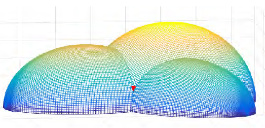
Figure 3: Intersection of Ellipsoids Locates Target at the Red Dot (Source: NAWCWD).
A variety of configurations is possible. In general, a minimum of three transmitter-receiver pairs is required to locate a target in three dimensions. That could be three receivers and one transmitter, three transmitters and one receiver, or any other combination forming three pairs. When more than one receiver is used, one of the receivers is designated as the master and the others must be time synchronized to that master receiver.
Alternatively, PCL receivers can use directional antennas to reduce the required number of receiver-transmitter pairs. When the receiver can locate and track the direction of the target, then the range to the target is provided by the point where the target direction intersects a single ellipsoid. Although this approach is simpler, it is usually less accurate because of uncertainty in the true target direction.
PCL ADVANTAGES
There are several advantages PCL radars have over conventional monostatic radars—one being that they are inherently covert. That is, unlike conventional monostatic radars, PCL radars have no transmitted beam to give away their position. That allows them to covertly acquire and track targets and pass the target position to other platforms. It is difficult for an adversary to apply countermeasures when they do not know that they are being tracked.
PCL radars can also be considered antistealth. Stealth technologies have been developed from L-band to X-band (1 to 12 GHz). However, FM radio operates in the VHF band (from about 80 to 108 MHz), where stealth materials and methods are not as effective. Therefore, stealth aircraft will have much larger cross sections (be less stealthy) against PCL radars using FM radio stations as their signal of opportunity.
The benefits of not having a transmitter also include smaller size, weight, system complexity, and reduced maintenance. This leads to lower cost of operation and simplifies implementation on mobile platforms. Mobility also contributes to PCL radars’ ability to operate covertly.
Another benefit of not having a transmitter is that a PCL radar adds no additional demand on spectrum resources. The EM spectrum is extremely crowded. Each radio or TV station, cell tower, microwave oven, etc., must license its piece of the spectrum with stiff penalties for spilling energy into adjacent frequency bands. This is also a problem for new monostatic radars because they must get approval to operate at a particular frequency with a particular bandwidth. However, since PCL radars use existing signals, this is not a barrier to fielding new systems.
PCL CHALLENGES
PCL radars have several unique challenges. One is the operator’s lack of control over the transmitter. The PCL radar operator has no control over the location, signal type, transmission power, transmission content, and other parameters—all which affect the radar performance. For example, FM radio is a commonly-used signal of opportunity, but the radar operator has no control over the type of programming from any particular station, yet the programming significantly affects radar performance. The worst format is voice because of pauses during which there is no signal. One of the better formats is rock music because it is more continuous, with fewer pauses or gaps.
Another significant challenge is isolation between the reference signal (direct path to receiver in Figure 2) and the much smaller target echo. The direct-path signal is typically many orders of magnitude stronger than the target echo. If even a very small component of the reference signal is received by the target receiver, it can degrade or even prevent target detection.
Some of the methods used to isolate the signals include the following:
- Physically blocking the signal antenna with a building or hill. This is most appropriate with fixed-site PCL radars rather than mobile.
- Using a signal canceler that coherently cancels the reference in the receiver prior to signal detection. The process is similar to that used in noise-cancelling headphones except that it operates at microwave frequencies rather than audio frequencies.
- Using a null-steering antenna. (This is described in more detail in the Antennas section of this article.)
- Using filtering to isolate a Doppler-shifted target signal from the nonshifted reference signal. The signal from moving targets will be shifted in frequency, which can allow using a bandpass filter to isolate it from the reference signal.
Generally, a combination of methods must be used because no single method will provide the necessary isolation.
Another issue is that the coverage area of a PCL radar is more complex than the coverage area of a monostatic radar. The maximum range of a conventional monostatic radar is given by the well-known radar range equation. The coverage area is nominally circular, the same in any direction, within the constraints of the antenna and the terrain.
The maximum range contour of a PCL radar is more complex. Instead of a circle, there is a range of shapes (illustrated in Figure 4) that depends on the radar range and L, the transmitter-to-receiver distance. We designate the radius of an equivalent monostatic radar range as Rm. This is the range a particular PCL radar would have if the transmitter and receiver were collocated.
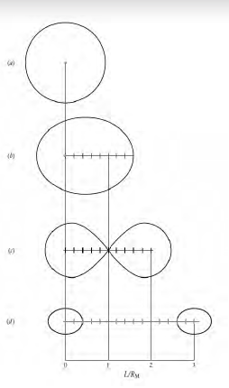
Figure 4: Ovals of Cassini Determine Detection Area (Source: Willis [1]).
Therefore, we can say that the relative locations of the transmitter(s), the target, and the receiver will significantly affect the ability to accurately locate and track the target. In another extreme case, when the target is near the line between the transmitter and the receiver, the effective cross section is significantly enhanced, but the ability to determine its location is greatly diminished (i.e., the target can be seen but not located).
In practice, the location of PCL receivers and the particular transmitters of opportunity used must be carefully chosen to optimize radar performance. In recent studies of PCL radar operation in areas with a high density of stations, methods for selecting the best radio stations for a given receiver location and expected target locations have been used. Computer-based methods have been developed to decide which radio stations to use for optimum performance in a given application [2].
ANTENNAS
PCL radars typically use antenna arrays rather than a single-element antenna. Figure 5 shows an example of a commercially-available PCL radar. Notice that the antenna consists of a circular array of eight dipole antennas. A review of PCL radars shows that this antenna arrangement is common. The details of the implementation will change, but the eight-element, circular array is often seen.
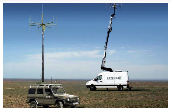
Figure 5: Commercial PCL Radar Example (Source: Hensoldt [3]).
It is also possible to use larger antennas to detect the target signal. A larger antenna provides higher gain and better angular resolution in the target direction, potentially increasing the distance the radar can see. The tradeoff is that a larger antenna is easier to observe, making the PCL radar less covert.
PCL Radar Challenge
Although we have just given a brief overview of PCL radars, it should be evident that they represent a unique threat unlike any other radar. Furthermore, it is unlikely that a PCL radar would be used in isolation. Rather, it seems most useful when integrated with other platforms, including conventional radars. To use Figure 1 as an illustration, it seems likely that PCL radars would be added to the environment, making it even more complex. The challenge is to develop countermeasures to an invisible threat in a complex environment.
T2OURNAMINT
Future battlefield engagements will occur in congested EM environments where radar and communication systems encounter intentional and unintentional interference from many sources simultaneously, including both adversarial- and friendly-force transmissions. The complex array of signals will cover a broad spectral range from communications bands to X-band radar and above. Furthermore, the signals are constantly changing in response to the changing EM environment and adversarial responses.
With a few exceptions, new weapons systems are typically tested one on one against specific threat systems. While such testing provides useful information, it does not provide insight into performance in a highly complex, dynamic battlefield with multiple, simultaneous, constantly-changing threats.
The T2OURNAMINT system at NAWCWD EWIL resides in the Electronic Combat Simulation Environment Laboratory. T2OURNAMINT brings a new level of fidelity to many-on-many, hardware-in-the-loop (HWIL) EW testing. It can be described as the hub of a digital electronic warfare (EW) arena. It provides a digital, high-fidelity threat environment into which multiple systems and systems of systems can be connected and interact at a signal-processing level. An overview illustration is shown in Figure 6.
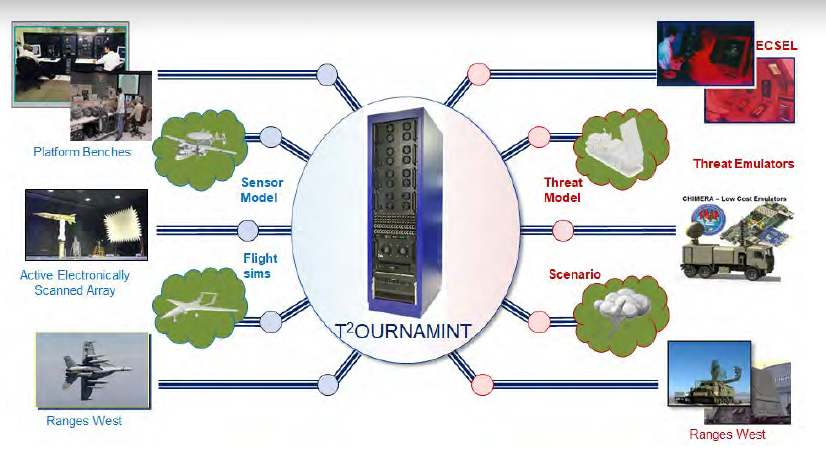
Figure 6: Connected Elements See Realistic Signals From All Other Nodes (Source: NAWCWD).
The T2OURNAMINT system is driven by a scenario generator that provides a single, all-inclusive mission scenario. In response to scenario details, T2OURNAMINT adds independent Doppler, range attenuation, and time-delay effects across all relevant frequencies. Closed-loop operation provides a dynamic, simulated battlespace environment in which systems interact in real time as they would in the field.
Other T2OURNAMINT features include the following:
- A frame generator maintains strict real-time operation to keep control over hardware devices and is synchronized to radar-coherent processing intervals to ensure simulation accuracy.
- T2OURNAMINT interacts at the real radio frequency (RF) and signal-processing level, and all input/output occurs at RF.
- Signal reflection from each object skin return caused by the PCL transmitted waveform is accounted for.
The T2OURNAMINT system is an ideally-suited testbed for developing strategies to counter the PCL threat. Therefore, a generic, easily reconfigurable, PCL radar is being developed to operate with the T2OURNAMINT system. This will enable the development of counter PCL radar strategies for new and emerging PCL radar threats.
CONCLUSIONS
PCL radars differ from typical radar threats in that they are bistatic radars in which no radar signal is transmitted. Instead, they rely on signals of opportunity, such as radio or TV stations, enabling them to operate covertly. This means that they can actively track targets of interest without alerting the target of their presence. Their relative simplicity also means that they are lower cost and can readily operate from a mobile platform.
The T2OURNAMINT system in the NAWCWD EWIL is an ideal platform for testing emerging anti-PCL strategies. As new strategies are developed, they can be tested in a realistic, closed-loop, many-on-many HWIL environment provided by the T2OURNAMINT system.
ACKNOWLEDGMENTS
The author wishes to acknowledge helpful comments and edits from his colleagues Ethan Julius, John Rice, and Ernie Rodriguez and insights gained from discussions with Duane Roth and Omar Ramos.
REFERENCES
- Willis, N. Bistatic Radar. Raleigh: SciTech Publishing Inc., 2007.
- Johnson, N. “Method for Real-Time Signal Selection for Passive Coherent Location Systems.” Ph.D. dissertation, University of Central Florida Orlando, FL, 2017.
- Hensoldt. “TwInvis – Passive Radar,” https://www. hensoldt.net/fileadmin/HENSOLDT_2019/Products/Radar_IFF_ Datalink/18-04-28_Hensoldt_TwInvis_Passive_ Radar_Flyer_v2d_highres.pdf, accessed March 2020.