Introduction
Like other contemporary energetic and propulsion technologies, electric propulsion—of which plasma thrusters are a subset—has been around for nearly a century. As Goebel and Katz, from the California Institute of Technology’s Jet Propulsion Laboratory, point out in their book Fundamentals of Electric Propulsion: Ion and Hall Thrusters [1]:
“Electric propulsion was first envisioned 100 years ago, and throughout most of the 20th century was considered the technology of the future for spacecraft propulsion. With literally hundreds of electric thrusters now operating in orbit on communications satellites, and ion and Hall thrusters both having been successfully used for primary propulsion in deep-space scientific missions, the future for electric propulsion has arrived.”
Although the basic concept of operation for plasma thrusters has not changed since their first demonstration, much advancement has been made over the years due to extensive research, design, testing, and engineering. Goebel and Katz consider ion and Hall thrusters “more modern electric engines that are finding increasingly more applications.” Further understanding the principles of operation and seeking ways to improve the technology for future advanced applications continue to be the challenges facing many private companies, government institutions, and universities across the world.
A Bite from U.S. History
Although much of the news about space travel in the 1960s was dedicated to Earth-based heavy rocket launches and landing a man on the moon, electric propulsion similarly enjoyed a flurry of activity and amazing successes (though much less celebrated) at the time. The first in-space demonstration of an electric ion thruster developed by the United States was achieved by NASA in early 1964 aboard the Space Electric Propulsion Test I (SERT I) spacecraft. One of two ion engines, carried into space by a Scout rocket, performed as expected and operated for a full 31 minutes, delivering high-velocity mercury ions from its thruster.
Later in 1970, to prove long-duration operation, SERT II demonstrated two ion thrusters, which performed for 3 and 5 months, respectively. In fact, the SERT II engines were operated intermittently from 1970 to 1981, with up to 300 engine restarts, while in-flight data were collected while in Earth orbit. The 1960s and 1970s showed considerable progress in electric propulsion by NASA, followed by a hiatus during the 1980s.
Work was revitalized in the 1990s with the NASA Solar Technology Application Readiness (NSTAR) ion thruster used aboard the Deep Space-1 (DS-1) spacecraft. Although size has grown over time for these thrusters with the SERT I mercury engine at a 10-cm diameter (and a 1.4-kW power demand and a 4,900-s specific impulse [ISP]), thrust and power demands for NSTAR at a 30-cm diameter have remained relatively unchanged (at a 2.3-kW power demand and a 3,100-s ISP). Furthermore, xenon gas, as opposed to toxic mercury, has now become a common fuel. Thrust-time (a measure of total impulse [IT]) has also increased considerably, as measured by 10,000 hours of working time and fuel consumption of 30 kg of xenon for NSTAR in the DS-1 spacecraft. Sovey et al. provide an excellent summary of NASA developments in their article “Ion Propulsion Development Projects in U.S.: Space Electric Rocket Test 1 to Deep Space 1” [2].
Electric Propulsion Vs. Chemical Propulsion Performance
During the last 5–6 decades, many different types of electric propulsion designs have been developed, tested, and deployed for space flight. Table 1 compares the properties of a small number of these devices along with chemical propulsion for reference. Electric propulsion reigns supreme in terms of ISP but provides low thrust levels compared to chemical propulsion. While chemical propulsion derives its energy from consumption of combustible organic and inorganic materials in a vented, pressurized chamber to accelerate a complex mixture of gas particles through a nozzle, electric propulsion relies on electrical or electromagnetic energy input to generate electrically charged fundamental particles with extremely high velocities (Figure 1).
|
Technology |
Isp (s) |
Thrust (lbf) |
Input Power (kW) |
Efficiency (%) |
Propellant |
|
|
CHEMICAL |
Solid Chemical Propellant |
150–270 |
Up to ~2 x 10⁶ |
– |
90–98 |
Binder-oxidizer-fuel compositions |
|
Solid Air-Breather Propellant |
400 |
– |
80–90 |
Air and fuel-rich compositions |
||
|
Liquid Bipropellant |
300–450 |
– |
90–98 |
Liquid oxygen (LOX)/liquid hydrogen (LIH) and various others |
||
|
ELECTRIC |
Resistojet |
300 |
~0.02–2 |
0.5–1 |
65–90 |
Hydrazine |
|
Arcjet |
500–600 |
0.9–2.2 |
25–45 |
Hydrazine |
||
|
Pulsed Plasma Thruster (PPT) |
850–1,200 |
<0.2 |
7–13 |
Teflon |
||
|
Hall Thruster |
1,500–2,000 |
1.5–4.5 |
35–60 |
Xenon |
||
|
Ion Thruster |
2,500–3,600 |
0.4–4.3 |
40–80 |
Xenon |
||
|
ADVANCED |
Variable Specific Impulse Magnetoplasma Rocket (VASIMR) |
3,000–12,000 |
~0.02–1.3 |
28–200 |
Up to ~70 |
Argon |
|
Dual-Stage Four- Grid (DS4G) Ion Thruster |
~15,000 |
~0.5 [6] |
250 |
~60 |
Xenon |
|
|
FUSION- |
Proton-Boron (p-B) Plasma Thruster |
~3,500a |
0.0011a |
0.022a |
~70a |
Hydrogen and boron |
| a Theoretical values based on initial experiments. | ||||||
![Figure 1: Conceptual Representation (A) and Design Cross Section With Electrified Grids (B) of an Ion Thruster [1, 2].](/wp-content/uploads/2019/11/en-figure-1-spring-2017-900x386.jpg)
With its comparatively high thrust, solid rocket propulsion is suited for earth-restricted launch, usually for heavy vehicles, such as missiles and space rockets. Energy is generated nearly instantaneously to create high thrust and acceleration, which quickly dissipate as the propellant is consumed. On the other hand, electric propulsion is desirable for vehicles already in Earth orbit or outer space, where low thrust and high particle velocity are used to constantly accelerate spacecraft and provide high fuel efficiency with exceptionally long operational times.
Chemical propulsion typically expends its stored energy on the order of seconds to minutes, while electric propulsion can last from months to years, eventually achieving and surpassing vehicle velocities achieved by chemical propulsion. Electric propulsion also offers restart and pulsing features, making it suitable for controlled and long-range space missions. Since the late 1900s, electric propulsion has been used, for example, to keep satellites in Earth orbit or to move them to higher orbits (i.e., station keeping and orbit adjustment) and conduct deep-space probe missions. Samples of the variety of electric thruster designs are shown in Table 1 and are further described in Table 2 [1].
|
Thruster Type |
Description |
Characteristics |
|
|
ELECTRO- |
Resistojet |
Electrothermal, fuel passes over resistively heated element, thrust is produced from exhaust velocity of |
Low Isp |
|
Arcjet |
Electrothermal, fuel passes through electrically |
Weak ionization, low Isp |
|
|
ELECTRO- |
Pulsed Plasma Thruster |
Electromagnetic thruster, |
Pulse rate determines thrust level, moderate Isp |
|
Hall Thruster |
Electromagnetic thruster, |
Moderate Isp, simple design |
|
|
ELECTRO- |
Ion Thruster |
Plasma thruster, ions accelerate through electrostatic grid |
High efficiency, high Isp |
|
ELECTRO- |
Variable Specific Impulse Magnetoplasma Rocket (VASIMR) |
Radio frequency (RF) magnetic thruster, ions generated by dual RF fields then accelerated through a magnetic nozzle |
High and variable Isp and thrust, predicted long life |
|
ELECTRO- |
Dual-Stage Four-Grid (DS4G) Ion Thruster |
RF-generated ion thruster, dual-stage accelerating screens |
High and variable Isp, low sputtering damage for extended component life |
|
FUSION- |
Proton-Boron (p-B) Plasma Thruster |
p-B fusion assisted plasma |
Compact, low power, low mass, moderate Isp |
Categories of Electric Propulsion
As shown in Table 2, electric propulsion can be divided into three categories: electrothermal, electrostatic, and electromagnetic. Electrothermal propulsion relies on heating a propellant gas stream to produce thrust, with little ionization of the gas (plasma formation). Operation of electrostatic and electromagnetic thrusters relies on the generation of a plasma stream, which is accelerated through electrified porous screens (grids, typically three) or a magnetic field (Hall effect), as shown in Figures 1 and 2, respectively.
![Figure 2: Concept Design for a Hall Thruster With Magnetic Fields for Accelerating Particles [1].](/wp-content/uploads/2019/11/figure-2-thruster.jpg)
Plasma streams of ions are created from a gas such as xenon (fuel, propellant), which is introduced through a hollow cathode (spark generator). In an electrostatic thruster, plasma ions collect in a chamber and are then accelerated past electrified grids, thereby increasing particle velocity to produce thrust. In a Hall thruster, or similar magnetic-assisted thruster, ions are accelerated past a magnetic field, eliminating the need for grids. Particle acceleration can be varied by the strength of the magnetic field, which is typically generated from electromagnets.
An exciting new enhancement to these designs is a concept recently proposed by Rocketstar LLC and developed by Fluid & Reason LLC, which uses proton-boron (p-B) fusion to enhance its ConstantQ thruster [3]. This fusion-enhanced plasma thruster, which is currently under development and testing, can be incorporated into electrostatic and electromagnetic designs, as discussed further in succeeding text.
Trending Toward Higher Specific Impulse
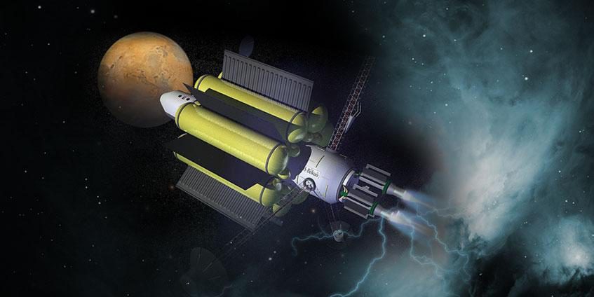
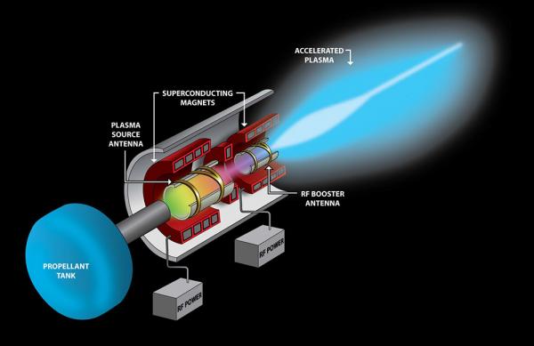
Recent examples of advanced thrusters under development and testing by NASA, universities, and foreign institutions are the VASIMR [4, 5] and Dual-Stage Four-Grid (DS4G) [6, 7] engines, which provide high ISP and predicted long life. VASIMR is an open design and uses radio frequency (RF) energy to ionize gaseous fuel along with superconducting magnets to accelerate ions through the nozzle, as shown in Figure 3. The variable impulse feature, which can allow vehicle acceleration or deceleration by changing the electrical current in the magnets, is expected to be most useful for deep-space applications. And because weight savings and fuel efficiency are critical to all space flights, NASA believes that the VASIMR engine could be powered by a limited supply of hydrogen fuel for travel to Mars, where it could then refuel for the journey back to Earth [8]. Deployment of VASIMR is still many years away, but development is progressing.
The DS4G ion thruster concept was inspired by controlled thermonuclear reactor (CTR) experiments that use multiple grids to direct high-energy particles. As illustrated in Figure 4, the concept employs four grids (A, B, C, and D), grouped in pairs. The spacing distance (hence, electrical potential) between the second (B) and third (C) grids provides acceleration of the ions. A typical three-grid system in electrostatic ion thrusters extracts ions from the source and simultaneously accelerates them. In these designs, particle accelerations are limited by beam acceleration electrical potentials of about 5 kV due to ensuing beam divergence, as well as impingement and erosion of grid material (sputtering, widening of grid holes), which ultimately limits ISP values to much less than 10,000 s (see Table 1).
Inspired by CTR designs and experiments with high-energy particles, DS4G decouples ion extraction and acceleration in two stages. As a result, reduced sputtering is realized on the first (A) and second (B) grids. Higher acceleration potentials (>>5 kV) can also be achieved for increased particle velocities between the second (B) and third (C) grids. Overall low beam divergence (6–12° compared to 12– 15° in typical ion thrusters and 40° in Hall thrusters) is also realized. Together, the European Space Agency (ESA) and the Australian National University’s Plasma Research Laboratory have conducted laboratory-based experiments on the DS4G thruster and have seen excellent results. Values for ISP as high as 15,000 s were measured, along with a thrust of 0.64 lbf using beam acceleration potentials in the range of 10–30 kV.
Challenges for Future Electric Propulsion
Because plasma streams are highly energetic, one can envision the need for materials that are potentially rare, exotic, and expensive to impart useful life to the components of these designs. Electrical and thermal insulating materials, particularly ceramics, are a necessity since issues such as grid erosion (sputtering), chamber erosion, cathode life, overheating of external components, and electrical effects on the vehicle can be limiting factors for overall performance and working life. Energy supply and demands, component weight, and external hardware (such as gas fuel tanks) are concerns for extended-life and extremely- long-distance missions, such as manned space flight (MSF) to Mars or solar system exploration.
As with many other technologies, miniaturization of plasma thrusters with high impulse and efficiency is also needed. Much like chemical propulsion, electrical propulsion seeks more advanced concepts and designs that can reduce size, mass, stress on components, and overall cost, as well as eliminate the need for external auxiliary components, increasing performance (ISP and thrust) and using less power. To address some of these needs, for example, NASA is currently promoting competition among universities and nonprofit institutions to support its CubeSat mission, which is directed toward demonstrating deployment of multiple small (10 cm x 10 cm x 10 cm) satellites into Earth orbit [9].
New Concept Coupled with Fusion
One concept being developed to address these challenges is the previously mentioned p-B fusion-assisted ConstantQ plasma thruster, which is a joint project between Fluid & Reason LLC and Rocketstar LLC [3]. In general, the concept fires a proton gun at solid B to create plasma ions that then accelerate through a thruster, as depicted in Figure 5. Like throwing a softball down a hallway with a turbine fan at one’s back, a boosting effect is created by the fusion reaction to increase acceleration of ions through the thruster chamber. Theoretically, the fusion reaction will also clear the exit nozzle of any recombining particles, as well as give exit thrust even after ions have left the apparatus. Fusion will continue to occur outside the system not only to free the exit area of any interference but also to increase particle velocity, and hence the delta-velocity of the vehicle.
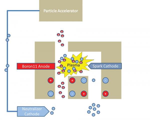
Fusion is the key to addressing higher velocity particle ejection (i.e., ISP) in the p-B-enhanced ConstantQ geometry thruster. It clears the way for the particles to move at an accelerated pace and gives a boost both behind and in front of the plasma thruster. Particles are rapidly flushed through the system. Because more power is generated compared to that at the start, due to the fusion reaction, the advantage on particle acceleration occurs on two fronts—the initial acceleration from the thruster and p-B fusion plasma and then the continued fusion outside the vehicle as particles exit the thruster.
The p-B Fusion After- Burning Effect
In a way, fusion acts as an after-burner for plasma engines. Typically, as ions exit a plasma thruster, they collect and obstruct the acceleration of new ions, thereby diminishing performance. This repulsive (clogging) effect is essentially eliminated with the presence of fusion. Fusion breaks the plasma ions into several smaller, extremely high velocity particles, which exit the thruster faster than the heavier plasma ions. The path is essentially cleared for subsequent ions to accelerate through the thruster. It is this after-burning clearance of space-charge build-up that is unique to the fusion-enhanced thruster, giving it the potential for higher performance in an overall smaller package.
In fact, most ion thrusters would benefit from a fusion after-burner since they face the challenge of releasing new ions into a repulsing exhaust cloud. All can benefit from clearing the waste exhaust sooner. However, some thrusters, such as the ConstantQ, get an extra benefit as the exploding ions from the fusion reaction create fast-moving positive fragments. As they race outward, they attract the negatively charged plasma components. The p-B-enhanced concept in the ConstantQ geometry retains a small number of extra electrons in its exhaust (a virtual cathode), adding to the pull experienced by the ions and reducing the repulsion. With the aid of fusion, ions (electrons) are dragged far from the craft, increasing the acceleration of additional ions leaving the engine.
The p-B-Enhanced ConstantQ Thruster
Beyond higher performance and vehicle delta-velocity, the p-B-enhanced ConstantQ concept potentially addresses other issues, such as size and fuel storage. There is no gaseous fuel to carry since protons can be generated from hydrogen molecules collected on the spacecraft (Brussard ramjet), from decaying radioactive material, or from other proton guns. A proton gun can be as small as a nickel, while the boron used could be the size of a quarter for small satellites. As shown in Figure 6, the plasma thruster that is married to the fusion apparatus is extremely small. And power requirements are low, as large magnetic fields are not needed in this design. Boron can be transported in stick or brick form since it is nonreactive in normal and man-rated environments.
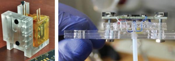
The ConstantQ thruster also addresses the lower cost concern. It uses a simple design for manufacturing and maintenance. Because the United States is the largest producer of boron in the world, feedstock is inexpensive and little threat to limited supply. Boron is also not a safety concern and is even less hazardous than a compressed gas cylinder. The use of boron also eliminates the necessity of scouring off-shore countries, especially those involved in military conflicts (such as Afghanistan), for exotic fuels. Additionally, the thruster design lends itself to advanced manufacturing techniques, such as additive manufacturing (i.e., three-dimensional [3-D] printing) for easy prototyping of complex geometries, if needed, and repair. Theoretically, if the spacecraft carried the necessary materials on board, or collected them along its journey, it could 3-D print parts necessary to fix any problems with the fusion thruster. Simple designs, such as the ConstantQ thruster, along with advanced manufacturing technologies, may someday eliminate the need for Earth-based repair solutions followed by resupply and repair missions to spacecraft. Lastly, since the feedstock is nonreactive, it is easy to transport, pack, and clear before flight.
Because the ConstantQ thruster design is so simple, it can be scaled easily to almost any size. It can be compacted to almost a two-dimensional (2-D) structure for use in space-limited applications, such as attitude adjusters on small satellites, or designed as a main power plant on an aircraft carrier. Conceivably, a fusion-enhanced thruster could be turned inward and placed on board a submarine for use as an efficient reactor, allowing submersion for extended periods. Due to the nature of the fusion reaction, and the fact that the system can be suspended in a magnetic field, the particles that are generated could be passed over an electron trap to create a current that provides power to electrical devices, siphoning power directly from the fusion reactor. In addition to being used as a power plant, the fusion-enhanced thruster could be used as a fusion torch to break up incredibly tough regolith on asteroids or planetoids and extract volatile materials, such as oxygen and nitrogen, supporting deep- space colonization or deep-sea mining.
With the enhancement of fusion to a plasma thruster, space transit times can also be drastically reduced. Conceivably, with a sufficiently large power plant, a Mars Transportation Orbiter could travel from the Earth to Mars in 10 days or fewer, where most of that time would be spent on acceleration and deceleration. If the craft were automated, the reactor optimized, and significant solutions to inertia implemented, a Mars cycler could leave earth and reach Mars in a few days. In short, other than general relativity and size constraints, there is potentially no limit to the speed and distance of the spacecraft with this fusion-enhanced thruster.
Conclusion
Electrical propulsion has certainly gained a lot of momentum since its conception nearly 100 years ago. Unlike chemical propulsion, which may have reached its practical energetic limit, electrical propulsion may continue to enjoy advances in increased performance, lower cost, smaller size, longer working life, improved safety, and reduced energy demands (and perhaps with no end in sight just yet). Accordingly, the upcoming century should prove interesting and fruitful as electrical propulsion continues to aid and expand the possibilities of future space travel.
References:
- Goebel, D. M., and I. Katz. “Fundamentals of Electric Propulsion: Ion and Hall Thrusters.” Jet Propulsion Laboratory Space Science and Technology Series, California Institute of Technology, March 2008.
- Sovey, J. S., V. K. Rawlin, and M. J. Patterson. “Ion Propulsion Development Projects in U.S.: Space Electric Rocket Test 1 to Deep Space 1.” Journal of Propulsion and Power, vol. 17, no. 3, pp. 517–526, 2001.
- Craddock, Christopher, and Wesley Faler. “p-B Fusion Enhancement of Plasma Thruster Operation.” White paper and patent application, 24 May 2016.
- Chang-Diaz, F. R., et al. “The Development of the VASIMR Engine.” International Conference on Electromagnetics in Advanced Applications, Torino, Italy, 13–17 September 1999.
- Cassady, L. D., et al. “VASIMR Performance Results.” 46th AIAA/ASME/SAE/ASEE Joint Propulsion Conference and Exhibit, 25–28 July 2010, Nashville, TN.
- Bramanti, C., et al. “The Innovative Dual-Stage 4-Grid Ion Thruster Concept – Theory and Experimental Results.” Paper IAC-06-C4.4.7, published by the International Astronautical Federation, 2006.
- Walker, R., et al. “Initial Experiments on a Dual-Stage 4-Grid Ion Thruster for Very High Specific Impulse and Power.” AIAA-2006-4669, 42nd AIAA/ASME/SAE/ASEE Joint Propulsion Conference & Exhibit, Sacramento, CA, 9–12 July 2006.
- NASAexplores. “Propulsion Systems of the Future.” NASA’s Human Exploration and Development of Space Enterprise, published 15 May 2003; https://www.nasa.gov/vision/space/travelinginspace/future_propulsion.html, accessed 9 January 2017.
- NASA Goddard Space Flight Center. “Announcement of CubeSat Launch Initiative.” Solicitation Number NNH16ZCQ002O, 4 August 2016 (see also https://www.nasa.gov/content/about-cubesat-launch-initiative).
- Ad Astra Rocket Company. “VASIMR VX-200 Meets Full Power Efficiency Milestone.” Press Release 231110, 23 November 2010.
- Bering, E. A., et al. “Performance Measurements and Technology Demonstration of the VASIMR VX-200.” AIAA 2010-8669, AIAA SPACE 2010 Conference & Exposition, Anaheim, CA, 30 August–2 September 2010.


![Figure 4: Depiction of DS4G Concept [6].](/wp-content/uploads/2019/11/figure-4thrusters-600x288.jpg)