

an email newsletter released every month highlighting the latest articles, events, technical inquires, and voices from the community
Defeating Passive Infrared Motion Sensors

Posted on April 3, 2018 | Completed on April 1, 2018 | By: Powers Garmon, Ph.D.
What methods are there to detect, counter/spoof, and neutralize commercial off-the-shelf (COTS) passive infrared (PIR) motion sensors?
The Defense Systems Information Analysis Center (DSIAC) staff was tasked with researching solutions to detect, counter/spoof, and neutralize commercial off-the-shelf passive infrared (PIR) motion sensors. A list of possible active and passive countermeasures to defeat PIR motion sensors was compiled and delivered to the inquirer. DSIAC compiled the list with the assistance of subject matter experts at the Georgia Tech Research Institute.
1.0 Introduction
The Defense Systems Information Analysis Center (DSIAC) received support from subject matter experts (SMEs) from the Georgia Tech Research Institute (GTRI). DSIAC and GRTI completed literature searches on the Defense Technical Information Center (DTIC) Research and Engineering (R&E) Gateway and other scientific and technical information (STI) sources to find articles relevant to the inquiry topic. Closed technical inquiries and other DSIAC website sources (journals, web articles, SOARS) were also examined for relevant information. A list of possible active and passive countermeasures to defeat passive infrared (PIR) motion sensors was compiled and delivered to the inquirer.
2.0 COTS PIR Motion Detectors
A PIR is an electronic sensor that measures infrared (IR) light radiating from objects within its field of view. PIR sensors are often used in PIR-based motion detectors, which is one of the most common detectors found in household and small business environments due to their affordability and reliability. A PIR detector can function without having to generate or radiate its own energy. A PIR-based motion detector is typically mounted on a printed circuit board comprising the required electronics to interpret the signals from the pyroelectric sensor chip. The complete assemblage is within a housing attached at a site where the sensor can scan the area to be monitored [1].
2.1 Examples of COTS PIR Motion Detectors
A few providers and models of COTS PIR motion detectors were examined for specifications and technology. They are listed here.
Honeywell Intrusion
- IS3035 PIR [2]
- Covers a 40 × 56-ft area and 90° wide angle
- 12 VDC power requirement (9–15 VDC allowed)
- Depth × Height × Width (inches) = 1.71 × 3.86 × 2.24
- IS3050 PIR [2]
- Covers a 53 × 72-ft area and 90° wide angle
- 12 VDC power requirement (9–15 VDC allowed)
- Depth × Height × Width (inches) = 1.71 × 3.86 × 2.24
- IS216/IS216T [3]
- Covers a 40 × 40-ft area and a 90° wide angle
- Requires 12 VDC power supply
- Depth × Height × Width (inches) = 1.5 × 3.375 × 2.375
Doberman Security Products
- Motion Detector Alarm with Chime (SE-0104) [4]
- Protects an area 60° both horizontally/vertically and 15 ft from unit
- Select from 100-dB alarm or chime sound
- Adjustable 270° swivel mounting bracket
- Depth × Height × Width (inches) = 2 × 4.25 × 1.25
- Requires 9-volt battery
Leviton
- IPS02, IPS05, IPS06, IPS15 [5]
- Covers 900 ft2 and 180° 120 VAC power requirements
- Depth × Height × Width (inches) = 1.22 × 3.28 × 1.75
Unifore
- Wireless PIR Motion Sensor 433/868 MHz [6]
- Covers 40 × 40-ft area with 100° angle
- Powered by 2 AA batteries (1.5V)
- Depth × Height × Width (inches) = 1.85 × 4.29 × 2.56
2.2 Methods for Defeating PIR Motion Sensors
This section of the technical inquiry was prepared by SMEs from GTRI.
2.2.1 PIR Motion Sensor Description
Excerpt from “Select the Perfect PIR Motion Sensor“ by F. Katz [7]:
PIRs contain a number of components which must work together properly for optimal performance. The components of a PIR sensor are: a Fresnel lens, a pyroelectric detector (pyro), a combination amplifier/filter, detection logic circuitry, an electronic or electromechanical switch to indicate detection and an LED which provides a visual indication of the detection.
Excerpt from Vulnerability Assessment of Physical Protection Systems by M. L. Garcia [8]:
The PIR sensor basic principle of operation depends on the difference in IR energy between an intruder and the background. The sensor detects the presence of an object when its field-of-view is blocked by an object that has a different temperature than the background. As a passive device, the sensor does not transmit a signal. Instead, the sensor responds to the energy emitted by a human intruder, which is approximately equivalent to the heat radiated by a 50-watt light-bulb. The PIR sensor responds to either the heat energy emitted by a human body or changes in background radiation caused by a person blocking the background in the sensor’s field-of-view. Using a variety of lenses, the detection pattern is subdivided into the solid angular segments. The electrical signal varies when a heat source moves out of one solid angular segment into the next, providing detection of a heat source in motion. Logic circuitry is usually applied to the received signal to differentiate among various situations. If the signal pattern matches that of a person in motion rather than generalized heating and cooling, an alarm is generated. The PIR sensor is more sensitive to motion across the field-of-view than to motion toward or away from the sensor. By properly designing the optics, the PIR sensor’s field-of-view can be tailored to provide various coverage patterns.
KUBE Electronics Fresnel Lenses
- Spot lenses, such as the KUBE Electronics AG TR1004, are single-zone Fresnel lenses. They are aspheric lenses, and compression molded on thin HDPE sheets [9]. An example is shown in Figure 1.
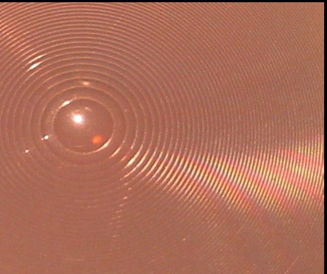
Figure 1: Kube Electronics AG TR1004 Single-Zone Fresnel Lens [9].
- A multizone Fresnel lens array employed with PIR sensors is depicted in Figure 2.
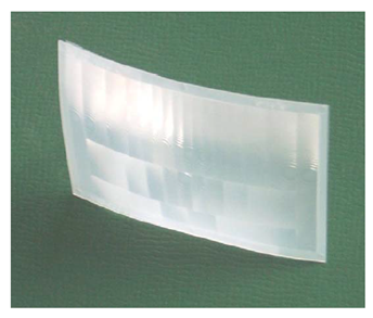
Figure 2: Kube Electronics AG DWA-305 Multizone Fresnel Lens Array [10].
- Detection zones (beams) for the DWA-305 are shown in Figure 3.
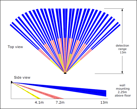
Figure 3: Top and Side Views of DWA-305 Fresnel Lens Array [10].
- Output signals generated by spot and a multilens sensor on detection are shown in Figure 4.
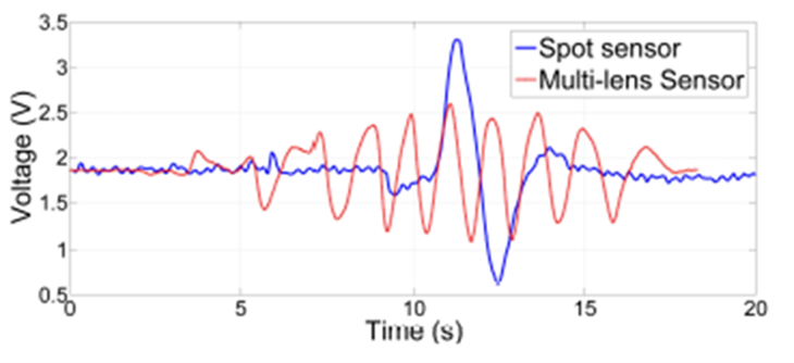
Figure 4: Example of Signals Collected From Spot and Multi-Zone PIR Sensors [11].
2.2.2 PIR Sensor Vulnerability Assessment
Excerpt from “Select the Perfect PIR Motion Sensor” by F. Katz [7]:
The most difficult test for a PIR motion sensor is when the target walks forward to the sensor, as the geometry of the lens design is such that only a few passive beams are crossed. Response is best when the target moves circumferentially around the motion sensor, keeping a fixed distance from the unit. Also, fast motion, close to the sensor or very slow are good ways to see design shortcomings in performance.
Excerpt from Vulnerability Assessment of Physical Protection Systems by M. L. Garcia [8]:
A PIR sensor’s probability of detection is a function of the magnitude of the difference between intruder temperature and background. Below the minimum magnitude of this difference, detection becomes difficult and unreliable. This minimum difference is usually referred to as the minimum resolvable temperature (MRT) difference. Probability of detection depends on other factors as well, such as the rate at which a temperature differential is introduced to the sensor detection zone and also intruder and background temperature gradients. Because the sensor is concerned only with temperature differences, intruders with a temperature colder than the background are detected as easily as intruders that are warmer than the background.
The detector elements in a PIR sensor can be subject to interference from various electromagnetic fields generated by equipment.
An intruder who appears to be the same temperature as the background is invisible to the sensor and could create a vulnerability. The sensor also can be defeated by very slow intruder motion.
Excerpt from “Defeating Passive Infrared Sensors” by H. Wardell [12]:
Insurgents began using Passive Infrared (PIR) sensors to bypass American electronic counter measures developed to defeat radio signal triggered IED (DefenseNews.com, October 29, 2007). I hypothesized that fitting a vehicle with shielding or jamming would make it undetectable to PIR sensors. The experiment involved using a 1/24-scale model car with heat source on a speed controlled mechanical track with PIR sensor. One hundred control tests were done to verify controlled variables. Fourteen tests were run to select the best shielding materiel and five tests were run to select the best jammer. One hundred tests each were run using best shielding and jamming materials as independent variables. The data collected did support the original hypothesis. In 100 of 100 tests, the shielding materiel kept the sensor from going off. Average shield temperature was 0.49°F lower than average background temperature, making the vehicle “invisible” to the sensor. Jamming kept the sensor from going off 76 of 100 times. The average difference between background and jammer temperature was 252.99°F, ~75°F over maximum operating range, “stunning” the sensor. Both shielding and jamming kept the logic processing elements of the sensor from working by presenting unvarying thermal energy. This made the sensor “think” nothing was happening.
2.2.3 PIR Motion Sensor Countermeasures
Active Countermeasures to Defeat PIR Motion Sensors
- Excerpt from “Researchers Show Ways to Bypass Home and Office Security Systems” by L. Constantin [13]:
A few families of motion detectors can be reset by pointing a source of light of a certain wavelength — infrared or near infrared — at them. This blinds the sensors for as long as the light source is pointed at them plus an additional three seconds…
- Excerpt from Panasonic’s PIR Motion Sensor brochure [14]:
PIR sensors may experience difficulty in sensing the target for the following conditions:
-
-
A shielding material, such as glass or acrylic, is held by the intruder in such a manner as to block his thermal signature from the sensor.
-
The intruder moves at slower or faster speeds inside the detection area than are specified by the PIR sensor manufacturer.
-
The temperature difference between ambient and the intruder is minimized.
-
The intruder moves very slowly until entering a detection beam, and then moves toward the PIR sensor while within the detection beam.
-
- Excerpt from an online forum reply to “Can Motion Sensors be Disabled by Lasers without Triggering the Alarm?” [15]:
It [the laser] would have to mimic the IR signature of the thermal energy in the sensor zone it was in when you first turned it on. The IR signature would have to match everything between the sensor and the barrier in that zone. You could obtain this with an IR camera and some fancy math to program the laser, but it would be tricky, if not impossible, assuming you could get the IR laser to even produce a signature something close to the thermal equivalent to room temperature. To have this level of control this would require a near-weaponized level of complexity in an IR laser. In short, using a laser would be the easiest way to trip the sensor, not blind it.
Passive Countermeasures to Defeat PIR Motion Sensors (Thermal Camouflage)
- Excerpt from “Thermal Signature Management” by M. S. Hall [16]:
Patents for military camouflage clothing also feature low emissivity surfaces in their designs. US7832018B2 for instance utilizes a breathable fabric to aid in the removal of heat through convection and a metallized surface to produce thermal camouflage [R. Schwarz, “Camouflage suit,” US 7832018 B2, 2010.]. The combination of a low emissivity surface and a breathable fabric structure that allows for large amounts of convective heat transfer to occur is fairly common in patent literature, especially in [literature on] thermal camouflage clothing. US 6127007 A also describes a camouflage garment with those described elements, but with dangling fabric strips with low emissivity properties that are intended to break up the shape of the wearer of the garment [ R. Cox, J. C. Edwards, J. S. Loyd, L. Watkins, “Infrared camouflage covering,” US6127007 A, 2000]. The low emissivity fabric strips [are] constructed of an inner low emissivity layer and outer layer that is thermally transparent and provides the necessary properties in the visible and NIR ranges. As can be seen by patent literature, low emissivity surfaces are common in thermal camouflage designs.
- Excerpt from “Quantum Stealth; The Invisible Military Becomes a Reality” by G. Cramer [17]:
Quantum Stealth is a material that renders the target completely invisible by bending light waves around the target. The material removes not only your visual, infrared (night vision), and thermal signatures but also the target’s shadow.
- Excerpt from “VATEC Sheet Makes Troops ‘Invisible’” by P. Fiddian [18]:
Low-observability technology so effective that it makes troops ‘invisible’ has been put through its paces during battlefield trials….
Named VATEC, this state-of-the-art sheeting can be reconfigured into shapes matching the local terrain. It reportedly allows military personnel to remain unobserved even when heat-seeking systems are deployed against them….
Invisibility camouflage trials involved not only British troops but also their US counterparts. They were carried out at the US Army’s vast Fort Benning facility….
VATEC was originally the work of Israeli firm Polaris Solutions but is now produced by ReadyOne Industries. According to the company’s VATEC factsheet: ‘VATEC kits and products are unique in that they allow individuals, equipment, and vehicles to become concealed by blending into the environment. By design, VATEC products enable the operators to render themselves and their equipment undetectable by mimicking specific terrain.
Combining lightweight properties with extreme flexibility and robustness, VATEC is available in various sizes/configurations. On that basis, it can potentially conceal a single troop, an armoured vehicle or anything in between.
- Excerpt from “Thermal Cloak Prevents Weapon Detection by Thermal Imagers” by Concept Group [19]:
Concept Group, Inc. has disclosed that the company is developing the new Insulon® Thermal Cloak™ heat barrier for use on automatic weapons. The barrier, which is attached to the fore-end of the weapon, uses a hair-thin Shaped Vacuum™ layer to prevent thermal imagers from seeing the weapon’s hot barrel, gas tube and sound suppressor after firing….
The soldier holding such a weapon, whose barrel, gas tube and sound suppressor are still hot from firing, is in grave danger from thermal imagers. They can easily “see” the high heat still coming off the weapon long after firing, even though the soldier is in complete darkness. That puts him in an extremely vulnerable position.
The new Insulon thermal cloaking technology eliminates this risk. A tube whose wall contains a hair-thin Shaped-Vacuum layer surrounds the barrel and gas tube. It can completely stop the convection of heat, cloaking the weapon’s barrel, gas tube and sound suppressor with a virtually impenetrable thermal shield. Even though the weapon’s fore-end parts are extremely hot – hundreds of degrees – the outside of the Insulon Thermal Cloak remains at ambient temperature, virtually invisible to thermal imagers. (For how it works, see http://conceptgroupinc.com/thermal.html)….
The Insulon Thermal Cloak is available today for custom development. It can be designed in virtually any size and shape.
For additional information on thermal camouflage combat systems, see “VATEC Concealment Solutions (VCS) Flexible Multispectral 3D Combat Camouflage System: Texturized Individual and Vehicle Camouflage by Polaris Solutions (Israel) and Readyone Industries Conceals your Visible-Light and Thermal/IR (Infrared) Signatures from the Enemy (Video!)” by D. Crane at the following link: http://www.defensereview.com/vatec-concealment-solutions-vcs-multispectral-3d-combat-camouflage-system-texturized-individual-and-vehicle-camouflage-by-polaris-solutions-israel-and-readyone-industries-conceals-your-visible-li/ [20].
- Excerpt from “Environmentally Dependent Countermeasures to Passive Infrared Detection,” by L. Peck and J. Lacombe [21]:
Abstract: Simple countermeasures against passive (thermal) infrared intrusion detection systems (IDSs) and thermal imagers were tested in winter by U.S. Army Special Forces soldiers working with personnel of the U.S. Army Cold Regions Research and Engineering Laboratory (CRREL). Under certain site conditions, the countermeasures were very effective, enabling intruders to pass undetected by the infrared IDSs or unnoticed by observers viewing thermal imagery of the site. An awareness of the interplay between environment, countermeasure, and sensor system is crucial both in identifying when a sensor system is vulnerable to countermeasures and in selecting the appropriate countermeasure. This paper explains which environmental factors during the Special Forces/CRREL intrusions determined the success or failure of a countermeasure. It also predicts the general effectiveness of similar countermeasures as a function of the operating environment of a thermal infrared sensor system….
Conclusions: Compared with other ground covers and with pavements, a snowcover presents certain advantages to an intruder attempting to avoid thermal detection though the use of countermeasures. Because the surface temperature of a snowcover typically has a smaller diurnal range and actually is stabilized (0°C) during snowmelt, it is a less dynamic thermal background for the intruder to blend with. Because a passive infrared intrusion detection system viewing a snowcover experiences smaller natural variations in thermal radiance, the intruder may have a larger margin between detection and nondetection; unless, that is, the PIR’s sensitivity has been increased specifically because the PIR is viewing a snowcover.
A snowcover presents two fundamental disadvantages. The first is that the thermal contrast between a person and a cold snowcover can be quite large, so the countermeasure has to work very well for it to be at all effective. The second is that the snowcover may retain a record that an intrusion has occurred, in the form of tracks in the snow, even if the intruder himself has avoided detection.
Four countermeasures have been described: two rely on matching the temperature of their background (cold-soaked burlap; poncho shelter) and two rely on substituting reflected thermal radiance for that of the intruder (fire shelter). The latter are more weather dependent in that the countermeasures only succeed if the reflected thermal radiance is indistinguishable from that of the background. Based on the results reported here, intruders and security personnel should be alert to situations of overcast sky and melting snowcover.
- Excerpt from “Active Camouflage for Infantry Headwear,” by K. W. McKee and D. W. Tack [22]:
Spectro Dynamic Systems Inc. has a US Army contract to develop an advanced face paint system that reduces the likelihood of individual soldiers being detected by thermal imagers (Jewish and Sweetman, 1997). A material is being developed that suppresses the thermal signature of exposed skin by diffusing thermal emissions with silver-coated hollow ceramic microballoons (cenospheres), averaging 45 cm in diameter, incorporated into a binder to produce a pigment with low emissive and diffusive properties. The microballoons act like a mirror, reflecting the surrounding environment and each other, thereby diffusing the emission of thermal radiation from the skin….
Active camouflage systems for infantry soldiers would greatly benefit stealth operations, especially considering that military operations in urban environments are becoming more prevalent. Conventional camouflage systems remain one colour and shape, however in urban environments the optimum colour and pattern could continuously change by the minute.
2.3 Other Related Articles
2.3.1 IEEE Articles
- “Pyroelectric Infrared Sensors-Based Distance Estimation” by P. Zappi et al. [23]
- “Human Tracking Using Ceiling Pyroelectric Infrared Sensors” by X. Luo et al. [24]
- “Tracking Motion Direction and Distance with Pyroelectric IR Sensors” by P. Zappi et al. [25]
- “Target Detection and Classification Using Seismic and PIR Sensors” by X. Jin et al. [26]
- “Fusion of Different Height Pyroelectric Infrared Sensors for Person Identification” by J. Xiong, F. Li, and J. Liu [27]
- “Detecting Direction of Movement Using Pyroelectric Infrared Sensors” by J. Yun and M. H. Song [28]
- “Multimodal Sensor Fusion for Personnel Detection” by X. Jin et al. [29]
2.3.2 Open-Source Articles
- “Human Movement Detection and Identification Using Pyroelectric Infrared Sensors” by J. Yun and S. S. Lee [30]
- “Advanced Motion Detector Using PIR Sensors Reference Design for False Trigger Avoidance” by Texas Instruments [31]
- “Using A CO2 Laser For PIR-Detector Spoofing” by R. H. M. A. Schleijpen and F. J. M. van Putten [32]
- “Pyroelectric Infrared (PIR) Sensor-Based Event Detection” by E. B. Soyer [33]
2.3.3 DTIC Articles
See the Appendix for a bibliography of relevant DTIC articles.
References
[1] Flammini, F., R. Setola, and G. Franceschetti. “Effective Surveillance for Homeland Security: Balancing Technology and Social Issues.” Chapman and Hall/CRC, 2013, https://books.google.com/books?id=wz1b2sQFxSsC&pg=PA415&lpg=PA415&dq=commercial+off+the+shelf+passive+infrared+motion+sensor&source=bl&ots=RvtwhlfTue&sig=EWHqFpNVafHzjNDX2KkiliCKlQ0&hl=en&sa=X&ved=2ahUKEwjA3a_0hY7dAhWJVN8KHXoYCJEQ6AEwEHoECAYQAQ#v=onepage&q=commercial%20off%20the%20shelf%20passive%20infrared%20motion%20sensor&f=false, accessed March 2018.
[2] Honeywell. “IS3000/DT8000 Series.” http://library.ademconet.com/MWT/fs2/IS3050/IS3000-and-DT8000-Series-Data-Sheet.PDF, 29 July 2016.
[3] Honeywell. “IS216/IS216T Passive Infrared Motion Sensor.” http://library.ademconet.com/MWT/fs2/IS216/IS216-IS216T-Data-sheet.PDF, 16 September 2011.
[4] Doberman Security. “SE-0104 Motion Detector Alarm w/ Chime.” Security Kits, https://www.dobermanproducts.com/products/se_0104.html, accessed March 2018.
[5] Leviton. “Product Bulletin: decora Universal Occupancy/Vacancy Sensors.” https://www.leviton.com/en/docs/Universal_Sensors_Product_Bulletin.pdf, 2013, accessed March 2018.
[6] Unifore. “Wireless PIR Motion Sensor 433/868 MHz.” https://www.hkvstar.com/item/wireless-pir-motion-sensor-433-868mhz.html, accessed March 2018.
[7] Katz, F. “Select the Perfect PIR Motion Sensor.” Security Dealer & Integrator, Fort Atkinson, vol. 30, issue 5, pp. 90, 92–93, May 2008.
[8] Garcia, M. L. Vulnerability Assessment of Physical Protection Systems. Elsevier Science, ProQuest Ebook Central, 7 November 2005, https://www.elsevier.com/books/vulnerability-assessment-of-physical-protection-systems/garcia/978-0-7506-7788-2, accessed March 2018.
[9] KUBE Electronics AG. “KUBE PIR Single Zone Fresnel Lenses.” Switzerland, http://www.kube.ch/downloads/pdf/kube_single_fresnel_lenses.pdf, accessed March 2018.
[10] KUBE Electronics AG. “KUBE Fresnel Lens Array DWA-30.5.” Switzerland, http://www.kube.ch/downloads/pdf/kube_lens_dwa305.pdf, accessed March 2018.
[11] Sujay N., et al. “PIR Sensors: Characterization and Novel Localization Technique.” Proceedings of the 14th International Conference on Information Processing in Sensor Networks, pp. 142–153, 2015. https://doi.org/10.1145/2737095.2742561, accessed March 2018.
[12] Wardell, H. “Defeating Passive Infrared Sensors.” Junior Division Engineering, http://www.csef.colostate.edu/2008_Abstracts/Wardell_Hannah.pdf, accessed March 2018.
[13] Constantin, L. “Researchers Show Ways to Bypass Home and Office Security Systems.” IDG News Service, 1 August 2013, https://www.pcworld.idg.com.au/article/print/522547/researchers_show_ways_bypass_home_office_security_systems/, accessed March 2018.
[14] Brochure. PIR Motion Sensor. Panasonic, https://na.industrial.panasonic.com/sites/default/pidsa/files/downloads/files/pir_motion_sensor_brochure.pdf, accessed March 2018.
[15] Schroeder. Reply to “Can Motion Sensors be Disabled by Lasers Without Triggering the Alarm?” Stack Exchange, 14 April 2016, https://security.stackexchange.com/questions/120483/can-motion-sensors-be-disabled-by-lasers-without-triggering-the-alarm, accessed March 2018.
[16] Hall, M. S. “Thermal Signature Management.” Thesis, Graduate Facility of North Carolina State University, Raleigh, NC, 2017, https://repository.lib.ncsu.edu/bitstream/handle/1840.20/34391/etd.pdf?sequence=1, accessed March 2018.
[17] Cramer, G. “Quantum Stealth; The Invisible Military Becomes a Reality.” Vancouver, B. C., 9 October 2012, http://www.hyperstealth.com/Quantum-Stealth/, accessed March 2018.
[18] Fiddian, P. “VATEC Sheet Makes Troops ‘Invisible’.” 21 March 2016, https://www.copybook.com/news/vatec-sheet-makes-troops-invisible, accessed March 2018.
[19] Concept Group. “Thermal Cloak Prevents Weapon Detection by Thermal Imagers.” https://www.defencetalk.com/thermal-cloak-prevents-weapon-detection-by-thermal-imagers-62182/, 26 January 2015.
[20] Crane, D. “VATEC Concealment Solutions (VCS) Flexible Multispectral 3D Combat Camouflage System: Texturized Individual and Vehicle Camouflage by Polaris Solutions (Israel) and ReadyOne Industries Conceals Your Visible-Light and Thermal/IR (Infrared) Signatures from the Enemy!” http://www.defensereview.com/vatec-concealment-solutions-vcs-multispectral-3d-combat-camouflage-system-texturized-individual-and-vehicle-camouflage-by-polaris-solutions-israel-and-readyone-industries-conceals-your-visible-li/, 21 June 2015.
[21] Peck, L., and J. Lacombe. “Environmentally Dependent Countermeasures to Passive Infrared Detection.” US Army Cold Regions Research and Engineering Laboratory, Hanover, NH, December 1998, www.dtic.mil/get-tr-doc/pdf?AD=ADA399453, accessed March 2018.
[22] McKee, K. W. and D. W. Tack. “Active Camouflage for Infantry Headwear.” DRDC, Toronto, CR-2007-023, February 2007, www.dtic.mil/get-tr-doc/pdf?AD=ADA477147, accessed March 2018.
[23] Zappi, P., E. Farella, and L. Benini. “Pyroelectric Infrared Sensors-Based Distance Estimation.” SENSORS, 2008 IEEE, Lecce, 2008, pp. 716–719. doi: 10.1109/ICSENS.2008.4716542.
[24] Luo, X., B. Shen, X. Guo, G. Luo, and G. Wang. “Human Tracking Using Ceiling Pyroelectric Infrared Sensors.” 2009 IEEE International Conference on Control and Automation, Christchurch, 2009, pp. 1716–1721, https://ieeexplore.ieee.org/document/4716542/, accessed March 2018.
[25] Zappi, P., E. Farella, and L. Benini. “Tracking Motion Direction and Distance with Pyroelectric IR Sensors.” IEEE Sensors Journal, vol. 10, no. 9, pp. 1486–1494, Sept. 2010, https://ieeexplore.ieee.org/document/5503973/, accessed March 2018.
[26] Jin, X., S. Sarkar, A. Ray, S. Gupta, and T. Damarla. “Target Detection and Classification Using Seismic and PIR Sensors.” IEEE Sensors Journal, vol. 12, issue 6, pp. 1709–1718, June 2011, https://ieeexplore.ieee.org/document/6086704/, accessed March 2018.
[27] Xiong, J., F. Li, and J. Liu. “Fusion of Different Height Pyroelectric Infrared Sensors for Person Identification.” In IEEE Sensors Journal, vol. 16, issue 2, pp. 436–446, Jan. 2016, https://ieeexplore.ieee.org/document/7152830/, accessed March 2018.
[28] Yun, J., and M. H. Song. “Detecting Direction of Movement Using Pyroelectric Infrared Sensors.” In IEEE Sensors Journal, vol. 14, issue 5, pp. 1482–1489, May 2014, https://ieeexplore.ieee.org/document/6697828/, accessed March 2018.
[29] Jin, X., S. Gupta, A. Ray, and T. Damarla. “Multimodal Sensor Fusion for Personnel Detection.” 14th International Conference on Information Fusion, Chicago, IL, 2011, pp. 1–8. https://ieeexplore.ieee.org/document/5977675/, accessed March 2018.
[30] Yun, J., and S. S. Lee. “Human Movement Detection and Identification Using Pyroelectric Infrared Sensors.” Sensors 2014, vol. 14, no. 5, pp. 8057–8081, 5 May 2014, http://www.mdpi.com/1424-8220/14/5/8057, accessed March 2018.
[31] Texas Instruments. “Advanced Motion Detector Using PIR Sensors Reference Design for False Trigger Avoidance.” TI Designs: TIDA-01069, October 2017, http://www.ti.com/lit/ug/tiducv3b/tiducv3b.pdf, accessed March 2018.
[32] Schleijpen, R. H. M. A., and F. J. M. van Putten. “Using a CO2 Laser for PIR-Detector Spoofing.” Proceedings SPIE 9989, Technologies for Optical Countermeasures XIII, 21 October 2016, https://www.spiedigitallibrary.org/conference-proceedings-of-spie/9989/99890K/Using-a-CO2-laser-for-PIR-detector-spoofing/10.1117/12.2240952.short?SSO=1, accessed March 2018.
[33] Soyer, E. B. “Pyroelectric Infrared (PIR) Sensor-Based Event Detection.” Master’s Thesis, Bilkent University, 2009, https://pdfs.semanticscholar.org/cc0d/856116d7b7cdee1a16fbb76302c54b3cb4a2.pdf, accessed March 2018.
DTIC Bibliography
McKee, K. W., and D. W. Tack. “Active Camouflage For Infantry Headwear Applications.” HumanSystems Inc., Distribution A, DTIC Accession Number: ADA477147, 1 February 2007.
Olsen, F. B. “Methods For Evaluating Thermal Camouflage.” Norwegian Defence Research Establishment, Distribution A, DTIC Accession Number: ADA456649, 1 December 2005.
Want to find out more about this topic?
Request a FREE Technical Inquiry!