


The current digital revolution is affecting almost every aspect of our lives. Many of the revolutionary changes, such as our latest mobile phones and the emergence of driverless cars, are obvious. Other changes, while much less visible, are no less important. The impact on product development has been especially profound. In particular, the emergence and popularity of digital, three-dimensional (3-D) technologies, such as computer-generated solid models and additive manufacturing (3-D printing) techniques, have greatly expedited the preparation of prototypes. Likewise, subtractive manufacturing techniques, such as computer numerical control (CNC) milling and laser cutting, have made prototype generation faster and less expensive, although these techniques have not received as much recent attention as additive manufacturing. But in either case, all of these production improvements are enabling multiple iterations of cost-effective prototypes to be made, which in turn has facilitated the development of exquisitely optimized manufacturing designs. And the solid model that results from these designs is the starting point of the “digital thread” that provides the digital data link through manufacturing and sustainment in model-based engineering (MBE) [1]. MBE is a process that is increasingly being adopted by many DoD and related organizations (including the National Defense Industrial Association [NDIA]) to manage the manufacture of complex products.
Rapid prototyping is defined as a group of digital techniques that facilitate the quick fabrication of a prototype physical part or assembly from a 3-D computer file. The first rapid prototyping technology was developed more than 30 years ago, when the first 3-D printer was invented [2]. Since then, many other 3-D printing techniques have been developed. These 3-D printing technologies, where a part is built up layer by layer, are collectively known as additive manufacturing. Other 3-D prototyping techniques, such as CNC milling and computer-controlled laser or water-jet cutting, are collectively referred to as subtractive manufacturing. With subtractive manufacturing, material is removed from a block or sheet until only the part remains. It is important to note that, in practice, it is often necessary to supplement digital prototyping techniques with manual methods, especially in the early stages of prototype development [3].
MANUFACTURING AND THE 3-D MODEL
MBE is a concept being adopted by many organizations to manage the manufacture of complex products. A 3-D computer-aided (CAD) model is the official data record and forms the starting point of the previously mentioned digital thread. It is produced during the concept and design phases of manufacture and will progress through the manufacturing process to the product’s end of life (see Figure 1). Currently, two-dimensional (2-D) blueprints are often used to officially track changes while “unofficial” 3-D models are created from these as needed, with all the inefficiencies that this approach entails. Therefore, 3-D model development, aided by the creation of iterations of prototypes during the concept and design phases of an MBE manufacturing process, is increasingly important.
PROTOTYPE COMPUTER MODEL DEVELOPMENT
A 3-D CAD model is required before either additive manufacturing or subtractive manufacturing techniques can be used to create a physical prototype that is suitable for evaluation. High-quality solid modeling CAD programs, such as SOLIDWORKS, PTC Creo Elements/Pro, and Autodesk Inventor, have greatly decreased the time needed to create 3-D models. A solid 3-D model is assumed to have volume, and all the faces of the model are connected to other faces. Solid-modeling software usually has the ability to test structural integrity of the model using finite element analysis (FEA) and to perform other analyses [4]. Because the models are feature-based, their geometry can easily be changed to accommodate design enhancements.
A 3-D CAD model may be developed from “scratch” from design requirements, or it may be reconstructed from existing blueprints. Often, these blueprints do not represent the part exactly as the part has been adjusted or adapted during previous production runs. In some cases, only a physical part is available, which must be captured and adapted to meet current requirements (see Figure 2). To create a 3-D CAD model from an existing part of any complexity requires the use of either a contact or noncontact coordinate measurement machine (CMM).
A contact CMM could be a fixed-bridge CMM, an articulated measurement arm, or a laser tracker. All of these CMMs touch the part to make the measurement and collect individual points or streams of points. Particularly useful for model creation from these types of point measurements is feature-based reverse engineering (RE) software, such as DezignWorks or Point2CAD, which facilitates creation of CAD models from parts using measurement arms.
A smaller part is generally scanned with a noncontact CMM, such as a laser scanner or a structured light scanner. A laser scanner, which is often attached to a measurements arm, projects a laser line onto the part, which is captured by a sensor offset from the projector. The projected line is distorted by the part’s surface topography, thus providing information about its curvature. The line scans are referenced into the global coordinate system by the encoder readings on the arm. In the case of a structured light scanner, a 2-D pattern is projected onto the part surface, and the pattern’s distortion is captured by an offset image sensor. A surface point cloud is then computed from this distortion.
Point cloud data are generally collected and integrated in specialized RE software, such as PolyWorks or Geomagic Verify. The points are processed to reduce noise and remove duplicate and erroneous data and converted into a more compact polygonal model. It is usually necessary to extract the geometric primitives from the polygonal models and to replace freeform surfaces with CAD-friendly lofted or Non-Uniform Rational Basis Spline (NURBS) surfaces. The model can then be exported to solid-modeling CAD software for adjustment and numerical simulations.
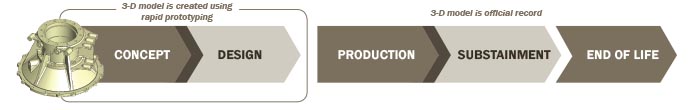
Figure 1: Model-Based Engineering (MBE).
CREATING THE PROTOTYPE
Once a digital model has been generated, the first prototype can be produced using either additive or subtractive methods. As mentioned previously, additive manufacturing builds up the part layer by layer whereas subtractive manufacturing creates the part by cutting away unneeded material.
ADDITIVE MANUFACTURING (3-D PRINTING)
The basic process of creating a prototype using additive manufacturing is straightforward. The CAD file must be converted into an appropiate file format, usually stereolithography (STL). In the process of generating an STL file, the 3-D model’s geometry is converted into a series of planar triangles, which are closer together in areas of curvature and further apart in flatter areas. The STL file is then imported into 3-D printing software, where it is sliced into 2-D sections so that it can be printed layer by layer. The resulting file contains the low-level program (G-code) that provides instructions to the printer. The exact form of the file depends on the particular technology of the printer and may include printing support material to prevent overhanging sections warping while the printing material cures.
Additive manufacturing has some important advantages for prototype creation. In general, parts can be quickly and (for small parts) inexpensively made, which encourages the creation of multiple iterations so that the optimum design requirements can be achieved. Additionally, complex parts are as easily produced as simple ones because they are all produced in the same manner, layer by layer. And printed parts can easily be fitted with electronic or mechanical components.
However, additive manufacturing does have some restrictions. The range of materials from which parts can be printed is limited, as is the size of parts that can be produced by typical commercial printers. And the cost of a 3-D printed part increases rapidly with size.
The following sections detail some common technologies that are categorized as additive manufacturing.
Stereolithography (SLA)
SLA, the pioneering 3-D printing technology, works by focusing an ultraviolet (UV) laser onto a bead of UV-curable resin to create a 2-D cross-section on the build platform. The platform is then lowered so the next layer can be cured. SLA printers produce extremely smooth parts with almost no stepping between the layers because of the high precision of the focused UV layer. Parts produced by SLA printers are particularly useful when the detail of the prototype is required to closely resemble the final, mass-produced part. The voids in the center of a part are typically filled with additional resin, and parts may require additional finishing/curing after the print has been completed.
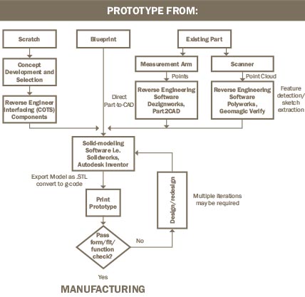
Figure 2: Prototype Development From Scratch, Blueprint, or Existing Part.
Fused Deposition Modeling (FDM)
The predominant solid-based 3-D printing technology is FDM, which works by extruding material layer by layer. The print head outlines the base layer of the object and then fills in the contour. After the first footprint layer is printed, the print head is raised slightly and deposits the second layer. The printer continues depositing one cross-sectional layer of the object after another (as illustrated in Figure 3). High-end FDM printers can produce large parts for prototyping. Parts can be made from plastics, generally acrylonitrile butadiene styrene (ABS) and polylactic acid (PLA). Overhangs are supported by layers of temporary material, which is easily removed once the print is complete. To achieve smoothness, parts must be post-processed by hand.
Powered Bed Printing
Powder bed printers work by spreading powder on a bed and then solidifying the layer with a liquid binder. There are many variations of this technology, but the most common one is the inkjet printer, which prints (colored) binder into the powdered material instead of ink. By using multiple print heads, it is possible to print in multiple colors. Overhangs, which may be a problem in other types of printing, are supported by the underlying powder. However, the prints tend to be brittle and require considerable cleanup to get rid of excess powder. In a similar manner to SLA prints, voids in the print are filled with powder.
Selective Laser Sintering (SLS)
SLS—and, similarly, direct metal sintering (DMLS) and selective laser melting (SLM)—use high-powered lasers to melt powdered particles. As illustrated in Figure 4, the powdered material is laid down and melted by the laser, and then the next layer is added. No binding material is required, and parts can be created out of numerous types of materials, such as metals, ceramics, and plastics. Further, the resulting parts can be as strong as conventionally manufactured parts. However, DLS, DMLS, and SLM printers are expensive and use potentially dangerous materials that require careful handling.
Polyjet Printing
Polyjet printers deposit a layer of UV-curable resin onto the print bed, which is instantly cured with a UV light, located on the print head. Overhangs are supported with gel, which is easily washed away after the printing is complete. The parts produced are strong and can include different colors and materials when produced with the appropriate resin. Many types of resin are available, and the print can resemble any material, from hard plastic to rubber. For example, a hard plastic inner shell, covered by a soft grip or protective layer of a rubber-like material, can be printed.
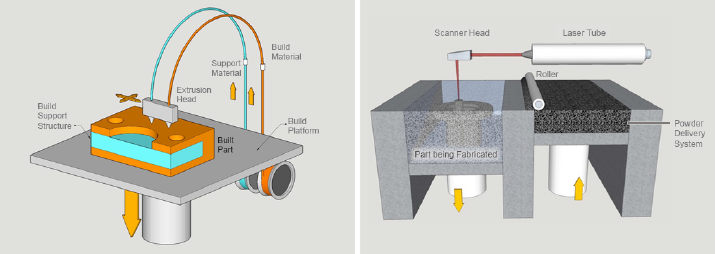
Figure 3 (left): Fused Deposition Modeling. Figure 4 (right): Selective Laser Sintering.
SUBTRACTIVE MANUFACTURING
Digitization has also profoundly enhanced milling and cutting capabilities, although this method has not captured the popular imagination to the same extent as 3-D printing or additive manufacturing. High-quality 3-D or sheet metal prototypes can be created directly from a processed computer model.
CNC Milling
Milling machines in their simplest form consist of a motor called a spindle that spins an end mill, which cuts away material from a block until the desired part remains. This block of the material is attached to a platform that can move in three or more directions with respect to the end mill. The operator removes material in pockets, revealing one feature at a time. Digitization has resulted in the replacement of many of the tasks of an operator with a computer and the creation of CNC mills.
The CNC milling operation is controlled by computer-aided manufacturing (CAM) software. Increasingly, CAM programs are sold as a module that works within solid modeling programs, such as Creo Elements/Pro or SOLIDWORKS. This software takes the 3-D model and processes it to create a series of instructions for the mill. However, CNC mill operation requires a considerable amount of skill and experience, with much operator interaction being required, depending on the material and the shape of the part being made.
When equipped with a suitable end mill, CNC mills can create parts from many materials, including steel, aluminum, titanium, wood, and plastic, making these mills highly versatile.
Computer-Controlled Laser Cutting
Laser cutting has emerged as an exciting technology that is useful both for prototyping and manufacturing. High-powered lasers are able to quickly cut complex metal profiles. Smaller CO2 lasers are sufficiently powerful to cut plastic and wood. Laser-cut parts are particularly suitable for sheet metal prototypes or may be part of the assembly used to create the prototype, depending on the application [2].
COMPARING ADDITIVE AND SUBTRACTIVE TECHNIQUES
A CNC mill, equipped with the appropriate end mill and cooling system, is capable of making parts in many more materials than 3-D printers. It is also able to achieve extremely high dimensional accuracy. However, 3-D printers can create parts with a great deal of complexity. Depending on the 3-D printing technology adopted, internal geometry can be just as complex as external geometry. Furthermore, it is possible to print preassembled assemblies, such as the assembled chain shown in Figure 5.
Additionally, CNC mills are capable of producing high-precision parts (less than 0.001 inch in size). On the other hand, the accuracy of 3-D printing relies heavily on the particular technology and is generally unable to meet the accuracy achievable by CNC mills. The general prototype iterative approach can be used to improve the accuracy of the part created by additive manufacturing. As shown in Figure 6, the part is printed and measured. The geometry of the solid model is then adjusted to compensate for those areas that are out of tolerance. The model is reprinted and selectively scaled until it provides a print of the required accuracy.
Machines that combine 3-D printing and CNC capabilities are becoming available. A part can be printed, and then select features can be machined for the highest accuracies.
A CNC mill, in the hands of an experienced operator, can produce smooth surfaces. Most 3-D printing techniques can as well; however, some 3-D printer techniques require post-processing to achieve a smooth finish.
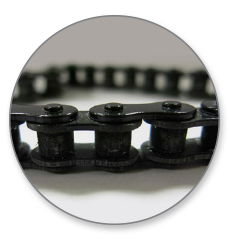
Figure 5: Assembled Chain Printed With Polyjet Technology.
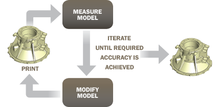
Figure 6: Iterating to Improve Printed Part Accuracy.
CHECKING THE PROTOTYPE
Once the prototype has been created, it is checked for form, fit, and function. If the part has been created with, for example, a powder printer, then it may be weak and/or brittle and thus not suitable for checking for function. In this case, resin casting may provide a part with sufficient strength to check function. A silicon mold can also be produced using the 3-D printed part and simple tools. With appropriately molded material, a strong functional part can be produced from a weak or brittle 3-D print.
If the part does not meet one or more of the checks, then adjustments are made to the model and another prototype is created. This process continues until the part can be shown to meet the design requirements. Several iterations are usually required. CAD software reduces the time required for 3-D model adjustment, and prototype parts can be produced quickly and relatively cheaply using additive and subtractive techniques, thus living up to the name “rapid prototyping.”
Once the prototype has met all of the product requirements, the part or assembly is ready to be manufactured from the finalized solid model. Manufacturing can take many forms, including 3-D printing, CNC milling, silicon molding, or injection molding, depending on factors such as the part’s material, dimensional tolerances, and number of parts required.
APPLICATIONS OF RAPID PROTOTYPING
The following two examples show how rapid prototyping was effectively used to develop 3-D solid models for products being developed under contract to Department of Defense (DoD) organizations. For these products, additive manufacturing was the most appropriate method of producing the prototypes to check form, fit, and function. For projects in which high-precision or extremely strong parts are required, subtractive manufacturing may offer a better solution. A third example is a 3-D printed “pilot,” which provides scale and a camera mount for a prototype Hoverbike, currently under development for the DoD via a DSIAC Core Analysis Task (CAT) (see related Hoverbike article later in this volume). All of these projects are being conducted by the SURVICE Engineering Company’s Aberdeen Technology Operation in Belcamp, MD.
HAWKEYE LOW-COST SCANNER
Hawkeye (shown in Figure 7) is a hand-held scanner currently under development for the U.S. Marine Corps as a joint venture between SURVICE and Corvid Technologies. The scanner is designed to be low cost by using a commercial-off-the-shelf (COTS) monochrome sensor and infrared (IR) laser projector scanner system. It can be used to perform battle damage assessment in the field, enabling Marines to determine if a combat vehicle has suffered structural damage.
The sensor and electronics components were reverse-engineered with a measurement arm in Part-to-CAD software (DezignWorks) so that the scanner housing 3-D computer model could be designed to accommodate them. The prototype housing was then printed using the SLA additive manufacturing technique in a material called Somos NeXt LV Grey, which is a highly durable material similar to a traditional thermoplastic. The housing was painted black with speckle for cosmetic purposes. Finally, the product name was silk-screened onto the upper housing component (as shown in Figure 8), and a connector was built into the scanner housing so that it could connect to a Microsoft Surface Pro 3 tablet for scan data processing.
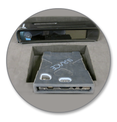
Figure 7: Hawkeye Scanner With Battery Pack.
A COTS high-capacity battery is included with the system to ensure that the scanner can be used in the field for extended periods. However, the battery was initially designed for office use and was not sufficiently rugged for use in the field. The battery was reverse-engineered using a laser scanner, and a rugged protective housing was designed in two sections: a rigid plastic inner section and a rubberized shell. The prototype case was printed on a Polyjet printer, which has the capability of printing material of two textures and colors (as shown in Figure 9).
Small adjustments are currently being made to the scanner housing and battery case solid-models to ensure that they are suitable for injection molding. After the initial expense for the preparation of the aluminum molds, many high-quality housings can be produced at low cost by injection molding, thereby meeting one of the design requirements.
However, before the mold is created (using subtractive manufacturing techniques), the final designs will be 3-D-printed and used to create silicon molds for resin casting. This step will have two purposes. It will allow the design to be checked before the high-cost molds are produced, and it will allow the production of a small number of parts (from 10 to 25) that can be used for assembly procedures development before the larger volume of injection molded parts become available.
AIRCRAFT DAMAGE LOGGER
SURVICE developed the aircraft damage logger to use photographs to measure the size of defects in the engine ducts of stealth tactical fighter aircraft of the U.S. Air Force. High-performance computational algorithms are required to run on the mobile processing unit, quickly exceeding the computing capability of the included COTS computer tablet. Therefore, custom hardware was developed to provide complementary computational capabilities. In addition, the hardware includes supercapacitor technology, which powers a 6,000-lumen light-emitting diode (LED) flash to illuminate the measurement area, as well as projected lasers, which provide scale to the area. The unit housing the computer tablet and the electronic board must protect from shock and moisture so that the logger can be used in challenging environments. The front and rear views of the case, as well as the internal electronics, are shown in Figure 10. The rear view of the logger (center) also shows the protected port that is required for downloading the raw and processed data. AM
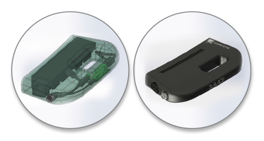
Figure 8: Hawkeye Scanner Housing Wireframe (middle) and Rendered Model (bottom).
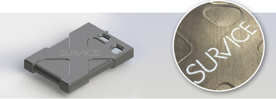
Figure 9: Hawkeye Rendered Battery Pack Case Model (left) and Polyjet-Printed Two-Material Battery Case (right).
Prototypes of the case were printed using a Polyjet 3-D printer. The case was printed out of two types of material, a photopolymer known as digital ABS (acrylnonitrile butadiene styrene), which forms a protective high-quality plastic shell. The shell was overprinted by a rubber-like material, TangoBlack FLX973, which provides shock protection as well as grip for the device.
Once the final design was developed, a small number of loggers (approximately 10) were required to be manufactured. The most economical way to produce these loggers was by resin casting. In addition to having a far lower setup cost than injection molding, resin casting has many resin varieties, ranging from extremely soft to extremely hard. These resins are also heat-, water-, and impact-resistant and can also be colored as desired using pigments.
Silicon molds for resin casting are created directly from 3-D printed parts, and therefore resin casting forms are a highly useful and complementary technique to additive manufacturing. These master parts must be carefully prepared for the molding process by removing any residual imperfections, such as layering artifacts and scratches. This removal may be accomplished, for example, by coating the part with automotive primer, followed by hand-sanding. In addition, texturing can be added through the 3-D printing process or by post-processing. Special care must be taken with the finishing process because any residual flaws in the masters will show up in the resin-casted parts.
The next step in the resin casting process is the creation of the silicon molds. Molds are created by attaching a 3-D printed part to a base and placing a frame around it. Registration objects such as nonporous plastic bars are also placed on the base so that positive and negative molds can be registered together. The silicon material is poured around the part and allowed to cure, creating the negative mold. Small cones and cylinders are glued to the 3-D printed part to make provision for fill holes for pouring resin into the mold as well as for venting displaced air. Mold release is applied to the negative mold, and an extension is added to the frame. An additional layer of silicon is added to create the positive mold.
An ABS stimulant resin was used to cast the inner case. Once the resin is mixed, and before it is poured into the mold, it is placed in a vacuum chamber so that any bubbles are removed from the mixture. The positive and negative molds are placed in position, and the resin is poured into the void between the two through the fill holes. Resins generally cure at room temperature. The inner case is then removed from the mold and is ready to be overmolded in a negative mold made from a 3-D print of the combined inner and outer case. The cast inner case is installed in its matching locations in the mold, and the voids between the case and the mold are filled with a rubber stimulant resin. Because of the low volumes required, silicon molding thus presents an economical solution for manufacturing the Aircraft Damage Logger.
HOVERBIKE PILOT
The Hoverbike, a joint venture between SURVICE and Malloy Aeronautics, is a new class of tactical reconnaissance vehicle (TRV) currently in development for the DoD [5]. The vehicle, a one-third-scale prototype, shown in Figure 11, is designed to carry a single pilot and fly at a range and altitude similar to a traditional small helicopter, potentially transforming the way U.S. troops operate in difficult terrain. Its small size and potentially high maneuverability mean it could operate in far tighter spaces than a larger rotor-wing aircraft. Also, the military variant of the aircraft is expected to be able carry several hundred pounds of cargo in addition to the pilot.
In support of the Hoverbike development, a 3-D scale model of the civilian version of the Hoverbike was created. This model includes a model of the Hoverbike’s pilot, fondly referred to as Cyborg Buster. The pilot, which was designed to be printed on a consumer-grade FDM 3-D printer, is approximately 22 inches high and has semi-articulated movement in its shoulders, elbows, hips, knees and ankles. It provides scale to the prototype, showing how an adult person would look on a full-sized Hoverbike, and it also functions as a highly adjustable camera mount. Figure 12 shows a GoPro camera installed into the pilot’s head so that video footage can be captured from a pilot’s-eye perspective. This is an example of how simple 3-D printing can be used to complement prototype development.
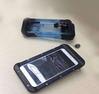
Figure 10: Aircraft Damage Logger Front (left), Rear Showing Camera and Flash (center), and Internal Electronics (right).
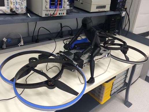
Figure 11: FDM-Printed Components on Hoverbike Scale Model.
CONCLUSION
Digital technologies, including solid-modeling, 3-D printing, CNC milling, and computer-controlled laser cutting have revolutionized prototyping in recent years. Modeling software is becoming less expensive and easier to use, and its ability to evaluate characteristics such as structural strength is becoming more sophisticated. Additionally, virtual models can be rapidly and economically tested for form, fit, and function by rapidly produced physical prototypes comprising sophisticated materials. Thus, these robust 3-D models are forming the origin of MBE’s digital thread, which will continue to be critical to the future of increasingly complex manufacturing in the United States.
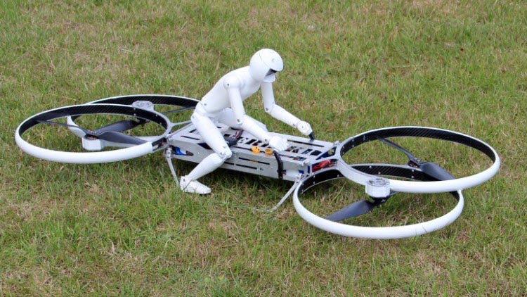
Figure 12: Hoverbike Scale Model With Video Camera Installed.
References:
- Luckowski, Stephen. “The Single Digital Thread – An Enterprise Approach to Establishing an Organic Base Manufacturing Ecosystem.” Presentation, U.S. Army Armament Research, Development and Engineering Center, Materials, Manufacturing and Prototype Technology Division, Picatinny Arsenal, NJ, 2015.
- Lipson, Hod, and Melba Kurman. Fabricated: The New World of 3D Printing. Hoboken, NJ: John Wiley & Sons, Inc., 2013.
- Hallgrimsson, Bjarki. Prototyping and Modelmaking for Product Design. London: Laurence King Publishing, 2012.
- Zheng Li, Jeremy. CAD, 3D Modeling, Engineering Analysis, and Prototype Experimentation: Industrial and Research Applications. Switzerland: Springer International Publishing, 2015.
- Wells, Carrie. “Hoverbike Could Be a Reality in Three to Five Years, Creators Say.” http://www.baltimoresun. com/business/bs-bz-hoverbike-20150629-story.ht… October 2015.