

an email newsletter released every month highlighting the latest articles, events, technical inquires, and voices from the community
Introduction to Guidance, Navigation, and Control (GNC)

Source: Patricia M. Beauchamp, Strategic Missions and Advanced Concepts Office, Solar System Exploration Directorate
Posted on October 18, 2022 | Completed on August 4, 2021 | By: Abraham Isser
Can you provide introductory summary on guidance, navigation, and control (GNC)?
This response was provided to broaden the technical knowledge of the inquirer’s technology management staff regarding guidance, navigation, and control (GNC), particularly GNC theory and technology applications related to aerial/space platforms and missiles. GNC is focused on the design of systems to control the movement and position of platforms such as missiles, space and airborne platforms, ground vehicles, and maritime and underwater platforms. GNC systems are constantly being improved to provide better target location accuracy and precision; faster attitude correction response of the guided platforms; and lower size, weight, and power of GNC electronics. Information regarding GNC-related research, development, simulation, and implementation onboard moving platforms was provided to the inquirer along with a bibliography to enhance the knowledge base of the inquiring agency. A literature search was conducted, and information sources are listed in the reference section. Specific test reports or other documentation are not provided in this inquiry response.
1.0 Introduction
An extensive literature search is provided on GNC technology and implementation and covers a wide range of GNC applications onboard airborne, spaceborne, ground, and maritime manned and unmanned platforms. GNC technology is a critical enabler for accurate navigation of moving platforms, precision weapon delivery, and precision guidance of missiles. This technology is constantly being improved to provide more accurate navigation and guidance, faster response times, and enhanced platform control. The future battlefield will demand high-performance GNC systems to enable precision strikes with minimum collateral damage; coordinated flight control of swarm unmanned aerial vehicles (UAVs); and simultaneous maneuvering of multiple aerospace, ground, and maritime robotic platforms in tight, Global Positioning System (GPS)-denied engagement zones.
2.0 GNC Overview
2.1. Introduction
GNC is focused on the design of systems to control the movement and position of platforms such as missiles, space, and airborne platforms; ground vehicles; and maritime and underwater platforms. GNC systems are constantly being improved to provide better target-location accuracy and precision; faster attitude correction response of guided platforms; and lower size, weight, and power (SWaP) of GNC electronics.
Guidance involves the vehicle’s current location and trajectory to a designated target, as well as desired changes in its velocity, rotation, and acceleration for following that path.
Navigation involves the vehicle’s location and velocity (its state vector) and its attitude (angular position in space).
Control involves the application of steering controls needed to execute guidance commands while maintaining platform stability and smooth travel to the target.
A typical GNC block diagram is shown in Figure 1. The guidance system can include a man-in-the-loop or an automatic trajectory generator. The control system includes a main system controller that can control the trajectory of the platform and correct its state vector based on external disturbances such as wind, ocean waves, or other environmental effects. The navigation systems could be based on the Global Navigation Satellite System (GNSS) or on optical star trackers in a GPS-denied environment.
Figure 1: Block Diagram of a Typical GNC System (Source: DSIAC).
Classical guidance laws, with proportional navigation (PN) being the most prominent example, had proven to be effective homing guidance strategies up through the early 1970s. (See Section 2.3.4 for a discussion of PN.) However, by the mid-1970s, the predicted capability of future airborne threats (highly maneuverable aircraft; supersonic and hypersonic missiles; tactical and strategic ballistic missiles and intercontinental ballistic missiles [ICBMs]; reentry vehicles, etc.) indicated that PN-guided weapons might be ineffective against them.
The application of optimal control theory to missile guidance problems as well as enhanced computing power had sufficiently matured by the early 1980s, offering new and potentially promising alternative guidance law designs. Most modern guidance laws are derived using linear quadratic (LQ) optimal control theory and applied to GNC systems via Kalman filtering (See Section 2.4) of various complexities to obtain accurate and fast analytic feedback solutions. Many of the modern formulations take target maneuver as well as nonlinear movement of attack platforms into account to deal with highly maneuvering target scenarios. (This fact is particularly true for terminal homing guidance.)
A classical GNC topology for a guided missile or a UAV toward an aimpoint or a target comprises the guidance filter, guidance algorithm, autopilot, and inertial navigation components. Each component may be synthesized by using a variety of techniques such as Kalman filtering for continuous tracking updates to achieve accurate platform guidance, and servo control for autopilot and flight path correction.
2.2 GNC Architectures
Federated Architecture. Traditional GNC computing systems follow a structured architecture with dedicated sensor systems. However, tactical missiles or UAVs require highly integrated, modular avionics. Integrating a highly accurate, small-SWaP GNC system into small airborne platforms is challenging. A typical GNC system is partitioned into the inertial navigation system (INS), GPS, sensor/seeker head, guidance and control computer (GCC), and telemetry module. Federated avionics architecture interconnects and transmits data between system submodules using a central avionics bus like ARINC 429, MIL-STD-1553B (Figure 2).
Figure 2: Federated Avionics Architecture [1].
The data connects between an avionics bus controller (ABC), GCC, flight control actuators, data link, sensor/seeker head, and telemetry systems as shown in Figure 2. This type of architecture guarantees isolation of system functional faults due to the federated design of each subsystem element. But since the structured design is not easily scalable to handle multiple subsystems, it requires a large SWaP and is inefficient and slow. This architecture also lacks technology reuse potential portability, and modularity, and has hardware obsolescence issues [1].
Integrated Modular Avionics (IMA) Architecture. IMA open-architecture GNC provides shared computing, large memory, fast communication link, and modular input/output (I/O) resources (Figure 3). The avionics functions are hosted on an IMA platform, which has a generic processor with communication and I/O interfaces. The core software provides the partitioning for multiple avionics functions and can be distributed across the architecture.
This architecture uses an advanced, digital ABC, like ARINC-629/659, and Avionics Full Duplex Switched Ethernet (AFDX) for fast data communication throughout the architecture. The functionality of an IMA-based GNC enables the integration of the INS, GPS receiver, and guidance and control telemetry on a single processing node (Figure 3). IMA open architecture is also modular, scalable, compact, and fast. Cooperative GNC approaches, under which two or more air platforms interact with each other, directly benefit platforms such as swarm UAVs, small-diameter precision munitions, cruise missiles and hypersonic missiles, and space satellites.
Figure 3: IMA Architecture [1].
2.3 GNC Challenges and Algorithmic Solutions
Advanced GNC systems face challenges in both GPS-available and GPS-denied environments:
- Miniature INS technology such as micro electromechanical systems (MEMS) gyros exhibit large angular drifts and are susceptible to external electromagnetic interference (EMI) disturbances, contributing to a coarse navigation solution and poor attitude accuracy.
- Navigation accuracy in real-world scenarios is vulnerable to response latency of communication nodes and data links and should be improved by data fusion between collaborating sensing nodes and fast-response data links such as free space laser communication links. Overcoming data registration and communication latency among cooperative sensing nodes is a fundamental prerequisite for effective fusion, enabling improvement to navigation and control accuracy.
- Safe navigation is challenging at low flight altitudes in complex environments and in GPS-denied environments. Most recent research efforts have focused on ways to improve GNC accuracy in GPS-denied environments. Optical stereo vision techniques and star-tracking sensing are emerging, promising technologies that could enhance precision GNC performance in these environments. Optical vision sensor systems are used as auxiliary information sources to improve navigation performance in GPS-denied environments. Main approaches for vision-aided inertial navigation are based on feature detection and tracking and sensor fusion using Extended Kalman Filtering for accurate tracking and attitude correction. Three-dimensional (3-D) feature positions and poses are calculated to update the platform state vector using parallel tracking and mapping (PTAM) algorithms, where a subset of key image frames is used to update feature mapping. To avoid the need for relative pose estimation, cooperative localization algorithms are being developed to enable processing of overlapping views taken by the vision sensors to create 3-D stereovision of target localization in real-time [2].
Multiple algorithmic solutions are under development for GNC accuracy enhancement. Accurate and timely fusion of distributed GNSS data with standalone GNSS observables, INS measurements, and vision-based estimates is critically important to improve navigation accuracy and integrity. These algorithms are applicable when a GNSS signal is available for all airborne-platform GPS receivers. The fusion of available GNSS/INS/GPS data (at formation level) and vision-based estimates enable safe navigation of platforms flying in GNSS-/GPS-denied environments.
2.4 UAV Swarm GNC
In a swarm UAV flight scenario where GNSS/GPS data are available and a UAV acts as “master” and one or more other UAVs act as “slaves,” the master state vector can be estimated based on relative sensing information coming from the slaves. The main logical steps are as follows:
- A differential GPS is used to estimate the baseline vectors among the master and the slaves in a stabilized North-East-Down (NED) reference frame. This method requires proper intervehicle communication since GPS measurements gathered by the slaves must be transmitted to the master UAV.
- Vision-based processing allows an electro-optic (EO)/infrared (IR) sensor hosted on a master UAV to detect and track slaves, thus providing line-of-sight (LOS) information in a camera-based reference frame (CRF).
- Sensor fusion is used to combine state vector baselines in NED as estimated by a differential GPS; LOS information from onboard EO/IR imagers; and magnetic, inertial, and standalone GPS measurements onboard the master, thus obtaining a more accurate and reliable navigation solution.
The angular position of the slave UAVs can be predicted based on master/slave GPS measurements and the master attitude. This prediction can be used to build a search window and thus optimize target geocoordinate accuracy. Since the slave UAVs’ configuration is known as well as their distance from the master, this information builds effective target templates to be used for correlation-based matching to achieve accurate azimuth and elevation angles in CRF. Angular accuracy can be improved by faster processing updates, higher-resolution EO/IR imagers, and accurate/fast-response INS/GPS systems [4].
3.0 Simulation of GNC of a Ground-to-Ground Missile with Varying Velocity
The engagement geometry of a ground-to-ground homing missile against a stationary target is formulated in Figure 4. In this scenario, the missile is supposed to be unpowered in the terminal guidance phase and is modeled as a point mass. To simplify the dynamics, the time-varying velocity V of the missile is assumed within a low Mach number range (Mach <2.0). The other variables of the missile are the normal acceleration command a, the flight path angle γ, and the position in the vertical plane (x, y). R refers to the relative distance between the missile and target. λ and ε represent the LOS angle and the lead angle, respectively. The forces acting on the missile are the lift L, the drag D, and the gravity mg, where m is the missile mass and g denotes gravity acceleration [5].

Figure 4: Force Vectors Surrounding Accelerated Missile [6].
The GNC simulation scheme is used to estimate mean velocity error and time-to-go error for a missile with time-varying velocities attacking a stationary target. A time-to-go estimation algorithm based on proportional navigation guidance law is fed into a Kalman filter to enable real-time flight control at varying velocities. To accurately predict velocity profiles, a velocity differential equation is used to calculate and numerically integrate downrange missile position in real-time. A third-order polynomial is introduced to fit the velocity profile and enable accurate calculation of future mean velocity.
At the beginning of each guidance loop, a future mean velocity is predicted and time-to-go information is updated. This is determined when a bias error based on the proportional navigation guidance law is established and fed into the missile navigation control system to accurately predict missile trajectory and minimize time-to-go and target location error. A set of simulations is used to analyze the relationship between different initial missile launch velocities. All initial missile launch angles are set to 60° and initial velocities are set to V = 200 m/s, 300 m/s, 400 m/s, and 500 m/s. Figure 5 provides travel time projections using estimation algorithm simulation results for different initial velocities. Figure 5(a) shows, as expected, all initial velocities having the same trajectory shape. Figure 5(b) presents velocity estimation for V= 200 m/s to 500 m/s and shows an increasing error in velocity estimation for higher initial velocities. Figures 5(c) and 5(d) illustrate the same trend for future velocity estimation and for time-to-go estimation.
Figure 5: Future Velocity and Time-To-Go Estimation Algorithm Simulation [6].
4.0 GNC Systems for Missiles
Guided missiles work by tracking the location of a moving target in space, chasing it down, and then finally hitting it accurately. A missile guidance system, like the air-to-air missile shown in Figure 6, includes all three GNC elements: navigation for tracking the current location of the missile, guidance for directing the missile toward the target using navigation data and target information, and control for applying guidance commands on the missile.
According to the profile of the target, guidance systems can be classified into two types: Go-Onto-Location-in-Space (GOLIS) and Go-Onto-Target (GOT). While GOLIS systems are usually limited to stationary or near-stationary targets, GOT systems prove to be highly effective in taking down both stationary and moving targets [7].
Figure 6: An Air-to-Air Missile Being Launched From an F-15 Aircraft (Source: U.S. Air Force photo by Master Sgt. Michael Ammons).
4.1 LOS GNC Systems
Commonly referred to as the LOS system (Figure 7), this type of control system consists of three components: a reference point (usually a radar station), a missile, and a target. Its mode of operation is straightforward: the radar station tracks the target continuously (regardless of whether it’s moving or not) and emits a beam leading up to the target. If the missile has enough fuel to reach the target, maintains a sufficient relative velocity, and stays on the beam, then it will make the hit.
Figure 7: A Radar LOS GNC System (Source: DSIAC).
The most glaring limitation of LOS systems is that they are rendered almost useless in situations where the target is using evasive maneuvers. Since most military airborne platforms are highly maneuverable, dodging LOS missiles is easy for them. Also, it is extremely difficult for an LOS missile to hit a target that’s approaching the reference point directly because the LOS missile is unable to make increasingly tighter turns to stay on target [8].
4.2 Pursuit GNC Systems
As the name signifies, the fired missile in the pursuit GNC system (Figure 8) automatically stays on the target and continues pursuing it until it makes the hit. As opposed to the LOS system, this guidance system involves only two components: the missile and the target. This system has two variants: Altitude Pursuit (AP) and Velocity Pursuit (VP).
In AP, the axis of the missile is kept pointing toward the target, whereas in VP, the velocity vector of the missile is kept pointing at the target. These two axes, the axis of the missile and its angle of attack, are usually not the same, as the missile sometimes skids as it flies towards the target.
Figure 8: Pursuit GNC Systems Are Highly Accurate and Hard to Avoid (Source: DSIAC).
4.3 Heat-Seeking Missiles
Installed at the head of the missile is either a tracking radar using an active homing algorithm locked on the target RF emission, or an IR optical sensor that tracks the heat signature of the missile plume. Missiles that use target emission signatures for target homing are referred to as fire-and-forget missiles. A few such missiles include the U.S. FGM-148 Javelin, the RAF Brimstone, Russia’s V-750 VM, and India’s Nag and Astra missiles.
Although the pure pursuit system is quite effective, it does have its limitations. For example, a missile that relies on the radar transmission of the moving target is rendered useless if the target, say a fighter aircraft, has deployed countermeasures (like chaff or corner reflectors) that interfere with the operation of the missile’s radar by saturating it with false information regarding its position.
Heat-seeking missiles also lose their operational usefulness if the RF or IR heat profile of potential targets is not known in advance. Furthermore, a friendly target could be hit when a heat-seeking missile is launched in a highly contested battle zone that contains enemy and friendly targets with similar RF or IR emission signatures. The lack of a man-in-the-loop in such systems makes them prone to hurting innocent or uninvolved third parties.
4.4 Proportional Navigation (PN)
PN is a guidance law that relies on the fact that two objects are bound to collide if their direct LOS does not change as the range closes. In a PN system, the missile stays on a trajectory with a constant bearing angle to the target (Figure 9). Unlike missiles with a pursuit guidance system, missiles with PN don’t pursue the target; they just keep moving in a carefully calculated direction (keeping the angle between them and the moving target, say, an aircraft, unchanged) with a constant velocity to eventually intersect the target.
One of the limitations of a PN system is its inability to cope with an accelerating target. Such a system is also highly prone to sensor noise. Various enhanced versions of PN systems were developed to include Augmented Proportional Navigation (APN) guidance systems. The AIM-9 Sidewinder, a short-range, air-to-air missile, employs a PN system.
Figure 9: In PN, the Missile Maintains a Constant Bearing Angle and Aims at a Point of Intersection With the Incoming Target (Source: DSIAC).
5.0 Kalman Filters
Also known as linear quadratic estimation, a Kalman filter employs an algorithm that uses a series of measurements observed over time, containing noise, and produces estimates of unknown variables that tend to be more precise than those based on a single measurement alone. More formally, the Kalman filter operates recursively on streams of noisy input data to produce a statistically optimal estimate of the underlying system state [8].
The algorithm works in a two-step process:
- In the prediction step, the Kalman filter produces estimates of the current state variables, along with their uncertainties.
- Once the outcome of the next measurement (necessarily corrupted with some amount of error, including random noise) is observed, these estimates are updated using a weighted average, with more weight being given to estimates with higher certainty.
The weights are calculated from the covariance, a measure of the estimated uncertainty of the prediction of the system’s state. The result of the weighted average is a new state estimate that lies between the predicted and measured state and therefore has a better estimated uncertainty than either alone. This process is repeated every time step, with the new estimate and its covariance informing the prediction used in the following iteration. Because of the algorithm’s recursive nature, it can run in real-time using only the present input measurements and the previously calculated state; no additional past information is required.
A simplistic, iterative Kalman filtering process involves continuous system state measurements, state vector estimation, computation of Kalman filter gain, and correction of system state error by minimizing the covariance matrix value [9, 10].
The Kalman filter has numerous applications in technology. A common application is for the GNC of vehicles, particularly aircraft, spacecraft, and missiles. It is a widely applied concept in time series analysis used in signal processing and econometrics. Kalman filters have been vital in the implementation of the navigation systems of U.S. Navy nuclear ballistic missiles, and in the guidance and navigation systems of cruise missiles such as the U.S. Navy’s Tomahawk missile and the U.S. Air Force’s Air-Launched Cruise Missile. It is also used in the guidance and navigation systems of the NASA Space Shuttle and the attitude control and navigation systems of the International Space Station [11].
Figure 10 shows the logic behind the Kalman filtering process. A prediction of the location of a moving target is shown in blue. The curve corresponds to a gaussian distribution of the uncertainty in the position of the target. A measurement of the estimated location of the moving target after a short period of time, Δt, is taken by sensors onboard the missile or by a ground radar, and the Gaussian prediction of the observation system in shown in orange. The Gaussian curve in the measurement corresponds to the uncertainty in the measurement process due to the noise of the observation system. By multiplying the probability distributions of the prediction and observation measurement, we can obtain an optimum Gaussian distribution curve that provides a better estimate of target location [12].
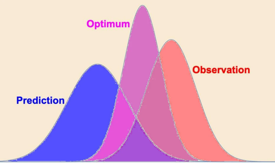
Figure 10: The Kalman Filter Combines Recursively an Uncertain Prediction of Target Position (Blue) With Imperfect Observation Data (Orange) to Produce an Optimal Position Solution With Lower Uncertainty (Source: Prof. Peter Lynch, School of Mathematics & Statistics, University College Dublin).
6.0 Summary
The complexities and uncertainties of the highly nonlinear dynamics of UAVs and fast-moving missiles pose challenges to modern GNC systems designers. The demand for accurate guidance and control and for precision strike is constantly increasing, and better GNC systems are being developed to improve GNC accuracy, precision, and response time. Autonomously guided swarm UAVs require precise flight coordination, and supersonic and hypersonic missiles require very fast trajectory correction updates and wide control system bandwidths.
Due to the unceasing and rapid progress made in electronics, communications, computation, sensing, driving and control, artificial intelligence (AI), and machine-learning sciences and technologies, great advances have been made toward autonomous, intelligent, and safe control of close-formation aerial platforms and fast-moving missiles. In the military, UAVs have been used to carry out missions such as reconnaissance, attack and damage assessment, etc. In various civilian applications, UAVs have also been widely investigated and applied for tasks such as search and rescue; goods delivery; surveying and mapping; power grid inspection; and forest fire monitoring, prevention, and control. Multiple UAVs with swarm/cooperative control technologies based on AI technologies have received great attention recently and have become popular topics in various UAV application fields [13].
Undoubtedly, UAV technology development will steadily enhance UAV autonomy, intelligence, and safety levels with autonomous, intelligent, and reliable/fault-tolerant decision-making and control of swarm flight formation and collision avoidance. The following research and development areas contribute to the advancement of UAV and missile GNC technology:
- Advanced autonomous control theories and technologies.
- AI techniques for UAV and missile GNC and multiple-UAV swarm/cooperative control.
- Fault detection and diagnosis, fault-tolerant control, and fault-tolerant cooperative control of UAVs and missiles.
- Trajectory planning and replanning, decision-making, and tracking techniques.
- Sense and avoid and obstacle-avoidance techniques.
- Swarm control theories and technologies.
- Robust formation/cooperative control under uncertain and disturbing environments.
- Related social and engineering applications for UAVs.
- Advanced Kalman filtering development and implementation for accurate GNC of missiles and precise trajectory prediction for supersonic and hypersonic missiles.
References
[1] Venugopal, R. B., T. Venkatamani, M. Kannan, and R. G. Venkat. “Integrated Guidance, Navigation and Control Systems for Tactical Missile Applications.” 2020 AIAA/IEEE 39th Digital Avionics Systems Conference (DASC), 10.1109/DASC50938.2020.9256792, 18 November 2020.
[2] Goel, S., A. Kealy, V. Gikas, G. Retscher, C. Toth, D. G. Brzezinska, and B. Lohani. “Cooperative Localization of Unmanned Aerial Vehicles Using GNSS, MEMS Inertial, and UWB Sensors.” Journal of Surveying Engineering, vol. 143, no. 4, 4017007, https://doi.org/10.1061/(ASCE)SU.1943-5428.0000230, 2017.
[3] Ekaso, D., F. Nex, and N. Kerle. “Accuracy assessment of real-time kinematics (RTK) measurements on unmanned aerial vehicles (UAV) for direct geo-referencing.” Geo-Spatial Information Science, vol. 23, no. 2, pp. 165−181, DOI: 10.1080/10095020.2019.1710437, 23 January 2020.
[4] Goel, S., A. Kealy, and B. Lohani. “Cooperative UAS Localization Using Low-Cost Sensors.” In ISPRS Annals of Photogrammetry, Remote Sensing and Spatial Information Sciences, III–1(July), pp. 183–190, https://doi.org/10.5194/isprsannals-III-1-183-2016, 2016.
[5] Wang, Y., W. Song, D. Fang, and Q. Guo. “Guidance and Control Design for a Class Of Spin-Stabilized Projectiles with a Two-Dimensional Trajectory Correction Fuse.” International Journal of Aerospace Engineering, 2015.
[6] Sun, G., Q. Wen, Z. Xu, and Q. Xia. “Impact time control using biased proportional navigation for missiles with varying velocity.” Chinese Journal of Aeronautics, vol. 33, no. 3, pp. 956-964, https://www.sciencedirect.com/science/article/pii/S1000936120300285, March 2020.
[7] Shneydor, N. A. Missile Guidance and Pursuit: Kinematics, Dynamics and Control. Horwood Publishing, Chichester, England, 1998.
[8] Strub, G., S. Dobre, V. Gassmann, S. Theodoulis, and M. Basset. “Pitch-Axis Identification For a Guided Projectile Using a Wind-Tunnel-Based Experimental Setup.” IEEE/ASME Transactions on Mechatronics, vol. 21, no. 3, pp. 1357–1365, 2016.
[9] Brown, R. G., and P. Y. C. Hwang. Introduction to Random Signals and Applied Kalman Filtering, Second Edition, John Wiley & Sons, Inc., 1992.
[10] Simon, D. Optimal State Estimation: Kalman, H Infinity, and Nonlinear Approaches. John Wiley & Sons, https://doi.org/10.1002/0470045345, 2006.
[11] Grewal, M. S., and A. P. Andrews. Kalman Filtering Theory and Practice. Upper Saddle River, NJ, USA, Prentice Hall, 1993.
[12] Julier, S., and J. Uhlman. “A General Method of Approximating Nonlinear Transformations of Probability Distributions.” Robotics Research Group, Department of Engineering Science, University of Oxford, 1995.
[13] Koifman, M., and I. Y. Bar-Itzhack. “Inertial Navigation System Aided By Aircraft Dynamics.” IEEE Transactions on Control Systems Technology, vol. 7, no. 4, pp. 487–493, https://doi.org/10.1109/87.772164, 1993.
Bibliography
Basseville, M., and I. V. Nikiforov. Detection of Abrupt Changes: Theory and Application. Englewood Cliffs, NJ: Prentice Hall, 1993.
Chwa, D., and J. Y. Choi. “Adaptive Nonlinear Guidance Law Considering Control Loop Dynamics.” IEEE Transactions on Aerospace and Electronic Systems, vol. 39, no. 4, pp. 1134−114, 2003.
Ding, S. X. Model-Based Fault Diagnosis Techniques. Design Schemes, Algorithms, and Tools. Springer, Heidelberg, Berlin, 2008.
Mani, T. V., S. Maitra, P. Bhanu Srinivas, K. L. R. Sekhar, S. V Lakshmi, and R. M. Guptha. “Integrated Modular Avionics for Missile Applications.” International Conference on Range Technology (ICORT), Balasore, India, 2019, pp. 1−5, 2019.
Menon, P. K., and E. J. Ohlmeyer. “Nonlinear Integrated Guidance-Control Laws for Homing Missiles.” AIAA-2001-4160, 2001.
Palumbo, N. F., and T. D. Jackson. “Integrated Missile Guidance and Control: A State Dependent Riccati Differential Equation Approach.” Proceedings of IEEE international Conference on Control Applications, pp. 243- 248, 1999.
Samadikhoshkho, Z., S. Ghorbani, and F. Janabi2-Sharifi. “Nonlinear Control of Aerial Manipulation Systems.” Aerospace Science and Technology, 2020.
Sharma, M., and N. Richards. “Adaptive Integrated Guidance and Control for Missile Interceptors.” AIAA-2004-4880, 2004.
Venugopal, R. B., R. S. Chandrasekhar, and N. Murthy. “BHVS: Linearized Analysis of Azimuth Transfer of Strapdown INS for Vertical and Slant Launch Applications.” AIAA Guidance, Navigation, and Control Conference, January 2017.
Windsor, J., M. Deredempt, and R. De-Ferluc. “Integrated Modular Avionics for Spacecraft: User Requirements, Architecture, and Role Definition.” IEEE/AIAA 30th Digital Avionics Systems Conference, Seattle, WA, 2011, pp. 8A6-1-8A6-16, 2011.
Zhou, J., and T. Wang. “Integrated Guidance-Control System for Beam-Riding Guidance Missile Based on Second Order Sliding Mode Control.” Journal of Astronautics, vol. 26, no. 6, pp. 1632−1637, 2007.
Zolghadri, A., D. Henry, J. Cieslak, D. Efimov, and P. Goupil. “Fault Diagnosis and Fault-Tolerant Control and Guidance for Aerospace Vehicles, from Theory to Application.” Series: Advances in Industrial Control, Springer, 2014.
Want to find out more about this topic?
Request a FREE Technical Inquiry!