

an email newsletter released every month highlighting the latest articles, events, technical inquires, and voices from the community
Fractal Radar

Source: https://lanl.gov/news-archive/publications/connections/2016/2016-11/in-other-news.php
Posted on December 19, 2022 | Completed on December 1, 2022 | By: Melinda Tourangeau
What are fractal radars, and how do they work?
The Defense Systems Information Analysis Center (DSIAC) was asked to deliver general information explaining fractal radar. DSIAC performed a literature search and delivered a list of publications/documents with summaries to the inquirer.
Fractal radars have been around for the last 20 years and are now just getting traction due to U.S. adversaries showing signs of using this technology. Fractal radar antenna arrays have dynamic element patterns that trace out the geometric functions of proprietary fractal equations programmed into algorithms. Fractal patterns occur organically in nature, making them good to mimic for energy applications like radar.
1.0 Introduction
Fractal radars earned their name because of the dynamic, fractal patterns that are rendered on a specialized antenna/radar surface (aka antenna topology) to achieve optimization in wideband radar applications. However, there is a whole other science behind fractal radars, which uses fractal equations to perform digital signal processing (DSP) on collected radar images to similarly distinguish, for example, man-made objects from natural ones. This science has been explored abundantly and has little to do with the antenna topology having a fractal pattern on its façade and more to do with the collected, digitized data that is ready for post-collection processing.
Another well-established application of fractals for radar is in image compression. The reader can easily imagine why this application would be beneficial for radar, especially remote antennas. This report focuses more on the topology of fractal radars rather than fractal equations to perform DSP. If the DSP explanation is desired, two sources are provided in the bibliography. This report provides an explanation of fractal radars to provide an elementary explanation for a lay person to understand, not to provide a heavy mathematical or empirically modeled explanation to the advanced technical community.
To begin the discussion, fractal radars are not emergent technologies. Discoveries were made in the late 1990s, and modern commercial-off-the-shelf (COTS) fractal antennas have been available for some time. One provider is Fractal Antenna Systems, Inc., out of Bedford, MA. Fractal Antenna Systems produces COTS fractal antennas like the ones shown in Figures 1 and 2.

Figure 1. Fractal Antenna Systems’ MANTA 4-BP [1].

Figure 2. Dimensions of a MANTA 4-BP [1].
The remainder of this report splits into two areas: (1) a fundamental explanation of radars (independent of fractals) and (2) fractals. The first topic is short, as much has been published on this subject and it is assumed the reader knows how radars basically work.
1.1 Radar Fundamentals
All radars transmit energy by emitting radiation and receiving reflections, subsequently focusing that received energy to perform postprocessing. Radar systems have evolved considerably, incorporating major advances in material processing; computation and signal processing; and the need for optimized size, weight, and power to make radars easy to transport, set up, operate, and fix in the field.
Additionally, the surfaces (i.e., shapes, curvatures, materials) of radar antennas have evolved from a single aperture to multielement arrays. Chunking up radar surfaces into elements has enhanced the applications and accuracy of radars considerably and provided for much smaller apertures (e.g., synthetic-aperture radar arrays). These days, technology provides for a lot of control on how elements are turned on and what frequencies they should emit, thanks to the electronics on the back end. For example, in active electronically scanned-array radars, the elements are energized electronically, rather than mechanically, to steer antenna beams. It is this technological maturity that enables fractal radars to exist.
Fractal radars operate the same as regular radars in that they still take energy from the environment and focus it for postprocessing. Fractal radars differ from basic radars by employing instantaneously changing topologies that trace out fractal geometric patterns. Any fractal pattern contains segments or edges like the ones that trace out the Koch snowflake shown in Figure 3. While Koch snowflakes are not used for fractal antennas, this graphic illustrates what is meant by segments or edges. The segments of the fractal pattern dictate the shape (i.e., size and location) of each element of a fractal antenna at any given moment. Segment is used carefully here because fractal antenna elements are no longer manifested materially (like in a phased-array radar) but rather electronically. All of this is explained in more detail later in this report.
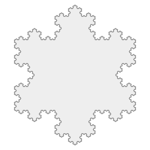
Figure 3. Segments or Edges of a Typical, Generic Fractal Pattern [2].
1.2 Fractals
Fractal patterns are unforced in nature, and many organisms leverage their fractal shapes to optimize energy collection or energy dispersal. A simple and worthy example found in nature is the flower, which both gives and receives energy. It needs to collect rainwater and sunshine, so its petal structure is optimized to do that. As the rainwater strikes the petals, it forces the petals to engage in a pattern dance to fold the water over the petals for prime collection. The petals bend toward the sun throughout the day in a dutiful pattern to maximize collection of the sun’s rays. The flower also needs to provide pollen, so its pistil is dutifully organized to make extracting pollen easy for bees. One need only replicate the intent of the flower’s patterns to optimize radar operations.
Fractal geometries have been previously defined by scientists around the world. Some more famous fractal patterns that have been mathematically defined and geometrically modeled are the previously mentioned Koch snowflake; the Sierpiński triangle; the Julia set; and, purportedly the most famous (due to its inherent beauty), the Mandelbrot set (Figure 4).
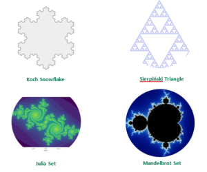
Figure 4. Mathematically Defined and Geometrically Modeled Fractal Patterns [2-5].
1.3 Fractal Radars
There are two primary benefits of fractal geometries for radar surfaces: (1) minimized sidelobes and (2) optimized power gain per element. Before launching into an explanation of why this is so, it is necessary to define the key structure of a typical radar—the array—and explain what is limiting about complete-aperture arrays.
A continuous or complete array is when the spatial frequencies of the array are continuous. A good example is a legacy radar paraboloid, as shown in Figure 5.
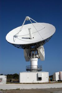
Figure 5. Radar Paraboloid U.S. Army C-Band Radar Dish Antenna [6].
Unlike these legacy, single-aperture, complete antenna arrays, modern radar antenna arrays utilize individual elements. A sparse array is when the spatial frequency spectrum is not continuous. A phased-array radar like precision acquisition vehicle entry (PAVE) phased-array warning system (PAWS) is a good example of a finite, sparse aperture antenna array (see Figures 6 and 7). The finite piece indicates the elements are physically molded into the antenna surface. They can be energized dynamically in random or calculated patterns.
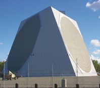
Figure 6. PAVE PAWS Array [7].
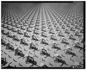
Figure 7. Surface Elements of PAVE PAWS Array [8].
Due to technological advances in machining antenna surfaces using microfilms and other materials for sensing radio energy, array elements can now be generated on demand and the size and shape of these elements is far more agile than with finite arrays like PAVE PAWS. This is the basis for fractal radars, and now perhaps the images of the fractal antenna systems’ MANTA 4-BP antenna should make more sense. Elements are created dynamically by stepping through a fractal geometric algorithm. Unlike the physical elements in Figure 7, in a fractal antenna, one cannot see the elements. The elements are highly dynamic, being energized (turned on) and turned off instantaneously according to a complex fractal calculation. Fractal elements allow for wider band/multiband use with lower mutual coupling between elements, which means they can be placed closer together with fewer sidelobe problems for the array. In addition, the fractal distribution of fractal elements allows near elimination of sidelobes and the same main beam performance at a wideband or at multiple bands. In other words, the spot of illumination is the same, even as frequencies change with the radar. It is almost as if the fractal radar is acting like a multiband laser with a uniform spot size, regardless of frequency.
According to Dr. Cohen, the best way to describe the surface of a fractal antenna array is with the legacy child’s toy LiteBrite™ where there is a fixed grid of locations for light pegs but the use of the location for a light peg, the color, and the pattern is variable. Once a fractal equation is programmed into an algorithm, the array is subjected to that calculation and the algorithm drives the on/off states of the light bulbs (or elements) instantaneously. The emitting area of an element at any given time (or with any programmed frequency) can be changed in space, unlike the elements of a finite array like the phased-array radar mentioned earlier. Furthermore, since the elements in a fractal array are generated electronically with photosensitive materials, the speed at which the elements can be energized is faster and the efficiency of the emitters is greater than with mechanical elements.
The fractal algorithm is the key to achieving this optimal radar pattern. It is a geometric function programmed into software and is commensurately dependent on both frequency and time. “These…patterns are the result of [an] equation or mathematical statement. Fractals are created by repeating this equation through a feedback loop in a process called iteration, where the results of one iteration form the input value for the next” [9]. The ability of a fractal radar algorithm to step through its many calculations instantaneously is made possible by modern computer processors (superfast) and sophisticated software programs. It turns out, as the algorithm is stepped through frequencies, the main beam stays focused and the sidelobes remain minimized. This is a profound and unique benefit of fractal radars, so it bears repeating that the shape of the beam is independent of the frequencies being radiated and the sidelobes remain minimized.
A synopsis of the use of fractal algorithms for antennas/radars can be found in “Fractals in Antennas and Metamaterials Applications:”
…using the fractal geometries [for the shape of] antenna elements. In recent years, there are many fractal shapes that have been proposed for such applications and the designed antennas have significantly improved antenna features such as smaller size, operating in multifrequency bands, with improved power gain and efficiency [10].

Figure 8. Fractal Geometric Pattern Being Stepped Through Time [11].

Figure 9. Conceptualization of Fractal Pattern Being Energized on the Surface of a
MANTA 4-BP Antenna Aperture (Source: M. Tourangeau).
The reader will need to engage the imagination to glean the meaning intended for this conceptualization. The surface of a fractal radar is subjected to a continuous algorithmic calculation of the fractal equation, thus stepping the surface through a dynamic pattern of elements or edges in time. The radar echo’s energy is received; collected; and, subsequently, aggregated for the desired application. This same depiction can be used to imagine transmission (i.e., the energy vectors are reversed). Again, the highly dynamic patterns of edges/elements force the energy waves to superimpose or cancel each other optimally to achieve the desired effect. It is difficult to sketch such a stepping through of a fractal pattern for changing frequencies, so the reader will need to visualize the changing fractal pattern with frequency.
One last word about fractal patterns for radiating applications is, in nature, there exists a special type of spiraling logarithmic pattern called the Fibonacci sequence or Fibonacci series. This pattern starts at zero (in the center) and continues with each subsequent number of elements calculated as the sum of the two previous numbers of elements in the sequence. It is also called the “Golden Ratio.” A common example of this in nature is the center of a sunflower. Another example is the flight of a bird of prey. This spiral pattern is considered nature’s way of being most efficient. The spiral path of a predatory bird of prey is executed with the least amount of loss in energy expenditure and with the most chance of finding and securing its prey. It is not too far a stretch to imagine a dynamically programmed spiral array of elements tracing this series being equally most efficient to collect or radiate radar energy. It certainly would explain the minimization of sidelobes and the optimization of power usage. If manifesting radar antenna aperture arrays is no longer limited by technology, then utilizing time-proven patterns like the Fibonacci series is a prudent approach to realizing desired radar applications.
2.0 Summary
Fractal radars leverage modern computer and material technology to fashion small antenna apertures that are electronically energized to follow a fractal geometric algorithmic pattern to instantaneously create elements that optimize gain and minimize sidelobes in wideband applications. The small form factor, efficient power use, and multiband operation make fractal radars ideal for multifunction electronic warfare and electromagnetic spectrum operation applications in the field. The algorithms are highly complex and proprietary, so one cannot see what fractal patterns are being used for fractal antennas. However, one can conceptualize the function of a fractal antenna by substituting a more commonly known pattern, such as a Koch snowflake. The best way to think about fractal radars is to imagine the legacy child’s toy LiteBrite™. Fractal patterns occur organically in nature and are designed to efficiently collect life-giving energy, such as sunlight and rainwater, or transmit energy, like pollen. These unique, repeating, recursive, inherently efficient patterns make them perfect for reflecting and collecting energy in commonly used radar bands for modern applications.
3.0 References
[1] Fractal Antenna Systems, Inc. “MANTA 4-BP Product Sheet.” https://www.fractenna.com/documents/Manta-4-BP_Product-Sheet_1.12.19.pdf, accessed 21 April 2023.
[2] Creative Commons. “Koch Snowflake 7th Iteration.” Wikimedia Commons, https://commons.wikimedia.org/wiki/File:Koch_Snowflake_7th_iteration.png, accessed 18 July 2023.
[3] Wikimedia Foundation, Inc. “Sierpiński Triangle.” Wikipedia: The Free Encyclopedia, https://en.wikipedia.org/wiki/Sierpi%C5%84ski_triangle, accessed 20 November 2022.
[4] Wikimedia Foundation, Inc. “Julia Set Triangle.” Wikipedia: The Free Encyclopedia, https://en.wikipedia.org/wiki/Julia_set, accessed 20 November 2022.
[5] Wikimedia Foundation, Inc. “Mandelbrot Set.” Wikipedia: The Free Encyclopedia, https://en.wikipedia.org/wiki/Mandelbrot_set, accessed 20 November 2022.
[6] National Aeronautics and Space Administration. “File: C-Band Radar-Dish Antenna.jpg.” Wikimedia Commons: The Free Media Repository, https://commons.wikimedia.org/wiki/File:C-band_Radar-dish_Antenna.jpg, accessed 29 November 2022.
[7] U.S. Corps of Engineers. “File: PAVE PAWS Radar Clear AFS Alaska.jpg.” Wikimedia Commons: The Free Media Repository https://commons.wikimedia.org/wiki/File:PAVE_PAWS_Radar_Clear_AFS_Alaska.jpg, accessed 27 November 2022.
[8] National Park Service. “File: Cape Cod Air Station—HAER MA-151-A—384568pu.jpg.” Wikimedia Commons: The Free Media Repository, https://commons.wikimedia.org/wiki/File:Cape_Cod_Air_Station_-_HAER_MA-151-A_-_384568pu.jpg, accessed 27 November 2022.
[9] Haggit, C. “How Fractals Work.” Howstuffworks, https://science.howstuffworks.com/math-concepts/fractals.htm, 13 April 2021.
[10] Krzysztofik, W. J. “Fractals in Antennas and Metamaterials Applications.” Fractal Analysis, DOI: 10.5772/intechopen.68188, edited by F. Brambila, https://www.intechopen.com/chapters/54899, 14 June 2017.
[11] Wolfram. “Koch Snowflake.” Wolfram MathWorld, https://mathworld.wolfram.com/KochSnowflake.html, accessed 1 December 2022.
Biography
Melinda Tourangeau is the executive director of the RVJ Institute, a 501(c)(3) center of excellence and research institute dedicated exclusively to excellence in the electromagnetic environment. She possesses advanced degrees in electrical engineering and business administration and is currently pursuing a Ph.D. in Education with an emphasis on organizational systems. Ms. Tourangeau is considered a subject matter expert in electromagnetic warfare (EW) and electromagnetic spectrum operations. She has authored numerous reports for the U.S. Department of Defense (DoD) and U.S. Congress and given presentations to audiences in Europe, Hawaii, Canada, and the United States. Her background emphasizes electro-optics, lasers, and semiconductor physics, as well as organizational and leadership systems. Her career includes serving as a DoD program manager for critical EW programs and serving as a spectrum engineer for Verizon Wireless.
Bibliography
Crespo-Miranda, W. F. Personal communication. Naval Surface Warfare Center, Crane, IN, 22 November 2022.
Fractal Antenna Systems, Inc. “Applied Innovation Enabling the Next Generation of Wireless.” Fractal Antenna Systems, Inc, https://www.fractenna.com/index.html, 27 November 2022.
Fractal Antenna Systems, Inc. “Nathan Cohen Bio.” https://www.fractenna.com/nca-cohen-bio.html, Fractal Antenna Systems, Inc, 29 November 2022.
Gupta, A. “Fractal Image Compression.” Northwestern University, https://users.cs.northwestern.edu/~agupta/_projects/image_processing/web/FractalImageCompression/index.html, accessed 29 November 2022.
Schmidt, D. (Director, Producer). Inner Worlds, Outer Worlds. https://www.imdb.com/title/tt2415372/, 2012.
Stewart, J. Personal communication. Naval Surface Warfare Center, Crane, IN, 22 November 2022.
Wornell, G. W. Signal Processing With Fractals: A Wavelet-Based Approach. First Edition, Upper Saddle River, NJ: Prentice-Hall, https://www.rle.mit.edu/sia/books/signal-processing-with-fractals-a-wavelet-based-approach/, 1996.
Want to find out more about this topic?
Request a FREE Technical Inquiry!